
The intent of this post is to get your Catalyst 9800-CL online with a trunked network interface. I will be writing another post to cover configuring WLANs, go over the new configuration model, and best practices.
First off, don’t let the length of this post scare you. I promise it really is simple if you follow the process I’ve outlined below. However, Cisco does not excel at developing OVA packages that work well in different environments. This has never been more true than it is with the 9800. The deployment process is wildly different between different versions of ESXi, or with vCenter. However, it is possible to successfully deploy the 9800 in several versions of ESXi, as well as vCenter. I’ll try to cover all the bases from my experience with deploying the Cisco Catalyst 9800-CL Virtual Wireless Controller (which is why this is such a long post).
Everything here is in reference to IOS-XE 16.12.1. The process may differ with newer versions. At the very least, I hope it gets more consistent between platforms.
NOTE: Read the networking section below, before you deploy the Catalyst 9800! Failure to do so may cause you to inadvertently create a network loop that will bring down the VM Host and/or the attached network.
Table of Contents
Catalyst 9800-CL VMware Version Support
The Catalyst 9800 v16.12.1 is officially supported on the following VMware versions:
- ESXi 6.0 and 6.7 (not 6.5)
- vCenter 6.0, 6.5 and 6.7
I have had OVA deployment issues (missing disk error on deployment) on ESXi 6.7 that are fixed in 6.7 Update 2. Most of the time if you attempt to deploy the OVA on an an unsupported version you will see a “A required disk image was missing” near the end of the deployment wizard, and/or the deployment will go much more quickly than it should (because it is not deploying the main disk). 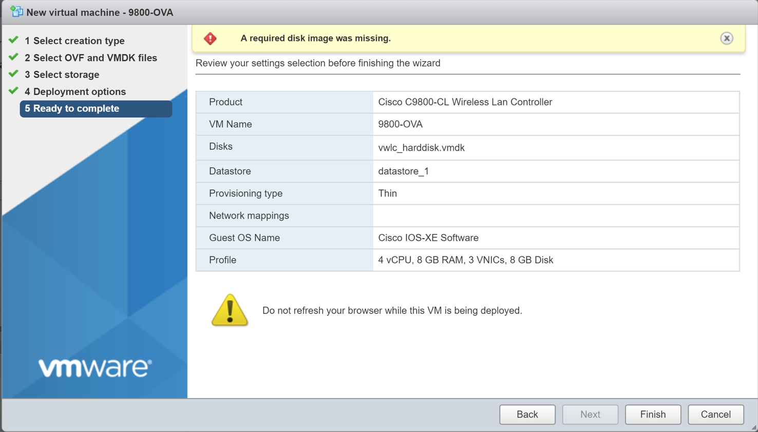
If you encounter this, you have several options:
- Use vCenter, if you have it. The OVA will usually deploy fine in vCenter, regardless of the version/patch level you are at.
- Use OVFTool (more on that below)
- Download and deploy the 9800-CL from the ISO instead of the OVA, using this method: https://www.cisco.com/c/en/us/td/docs/wireless/controller/technotes/8-8/b_c9800_wireless_controller_virtual_dg.html#id_90231
- Upgrade VMware to a supported version, which may or may not resolve the issue. This would be a last resort, as it is fairly simple to work around the error without upgrading VMware.
Important VMware Networking Information – Critical to the success of this process
Please read this section carefully. Failure to understand this section will likely cause a bridge loop that will bring down the VMware Host and/or the attached network. At the very least, it will cause the controller to perform very poorly, because it will be constantly looping traffic in the background.
By default, the Catalyst 9800-CL will deploy itself with 3 network interfaces. The purpose of each of these interfaces is as follows:
- Gigabit1: Out of Band Management (Service Port)
- Gigabit2: Main Network Interface for client traffic
- Gigabit3: Heartbeat interface for SSO HA
If you are planning on trunking your 9800-CL to the network (to allow multiple VLANs for clients), each of these interfaces MUST be on its own vSwitch! Remember, the Catalyst 9800 is basically a switch with wireless capabilities. Having more than one of these interfaces on the same vSwitch is like plugging two switches together using multiple links without a port channel.
In my opinion, most deployments will not need Gigabit1 and some will not need Gigabit3. There is not much point of an OoB Management Interface (Gigabit1) on a VM, in my opinion, and many deployments will not use SSO HA (Gigabit3). In our example, we will be deleting Gigabit1 and Gigabit3, and setting Gigabit2 as a trunked interface. Since only one interface will be used, we don’t need to worry about a network loop.
Important note: If you are going to delete interfaces, you must do so before the VM is powered on for the first time. On the initial boot, a bunch of scripts are automatically executed, and they appear to map specific services to each interface. I’ve tried to delete interfaces after accidentally powering it on, and have had bad luck. Just delete them before you power it on and save yourself the trouble.
Configure a VMware Port Group to Allow Trunking
- Select the Networking section on the left side of the screen and then click “Add Port Group” near the top
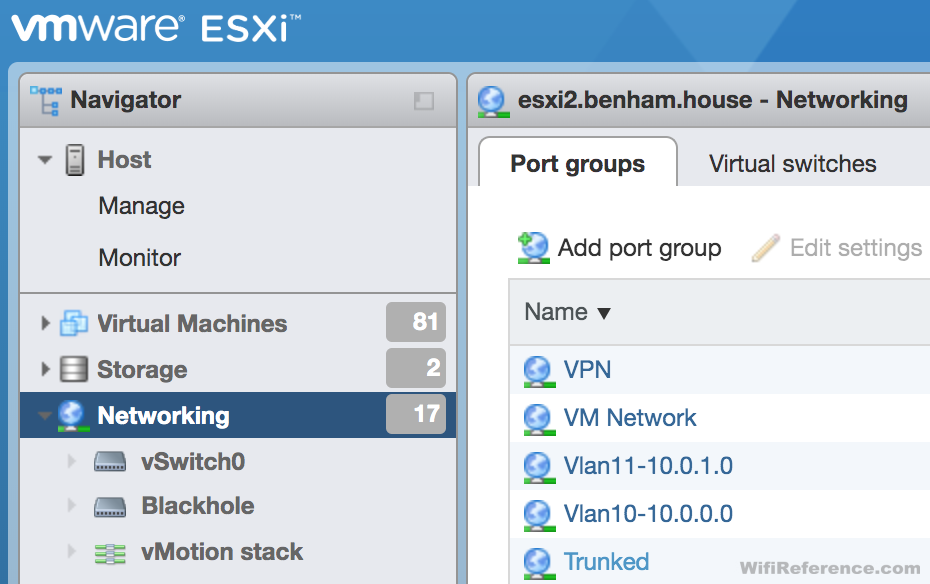
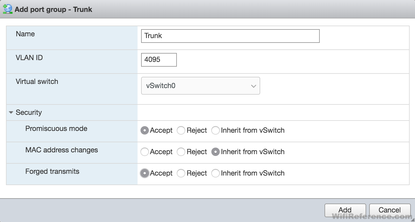
- Name the Port Group “Trunk” or something similar
- Set the VLAN to 4095 (this means allow all VLANs)
- Modify the Security settings to accept Promiscuous Mode and Forged Transmits (these are both necessary for the WLC to be able to pass 802.1q tags)
Note: You really should have promiscuous mode and forged transmits set to reject at the vSwitch itself. It is possible to create a broadcast storm if more than one VM with a trunked interface exists and these settings are enabled at the vSwitch. The settings at the port group will override the vSwitch settings.
Now you will see this Port Group in the list when you select the network for each interface during the OVA deployment.
Deploying the Catalyst 9800-CL using ESXi 6.7 Update 2.
I am showing the process with ESXi 6.7U2 specifically, because this version is able to deploy the OVA. You can try this process with other versions but you may encounter the “A required disk image was missing” error during deployment. If you do, please reference the VMware Version Support section above.
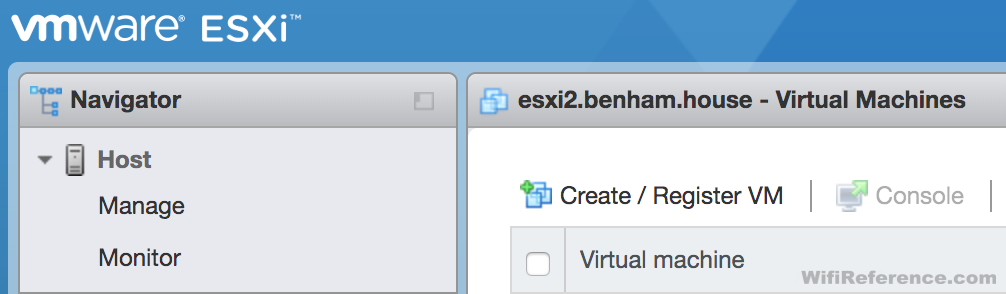
- Click on the Virtual Machines category on the left
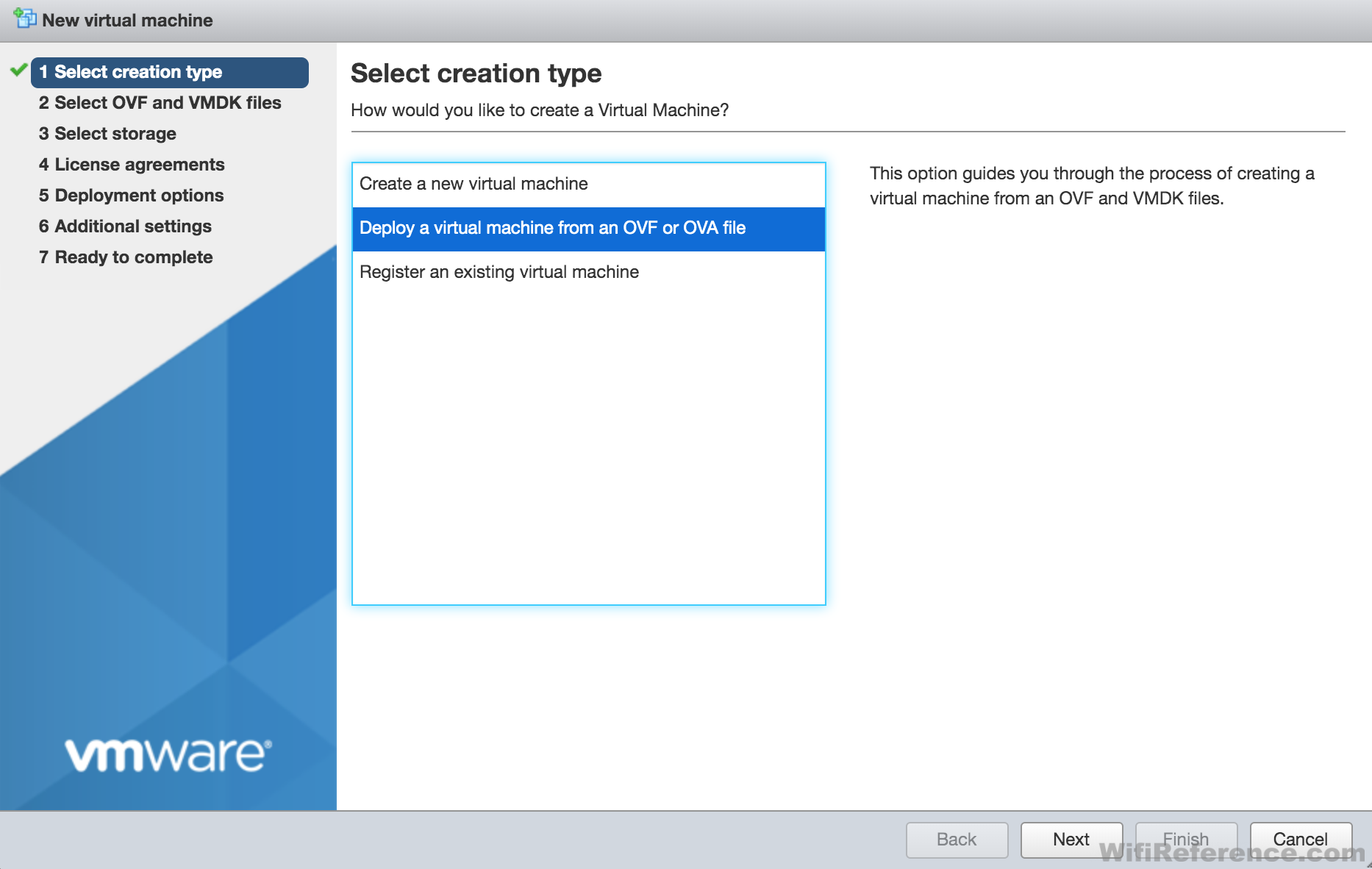
- Click Create/Register VM
- Select “Deploy from OVA/OVF
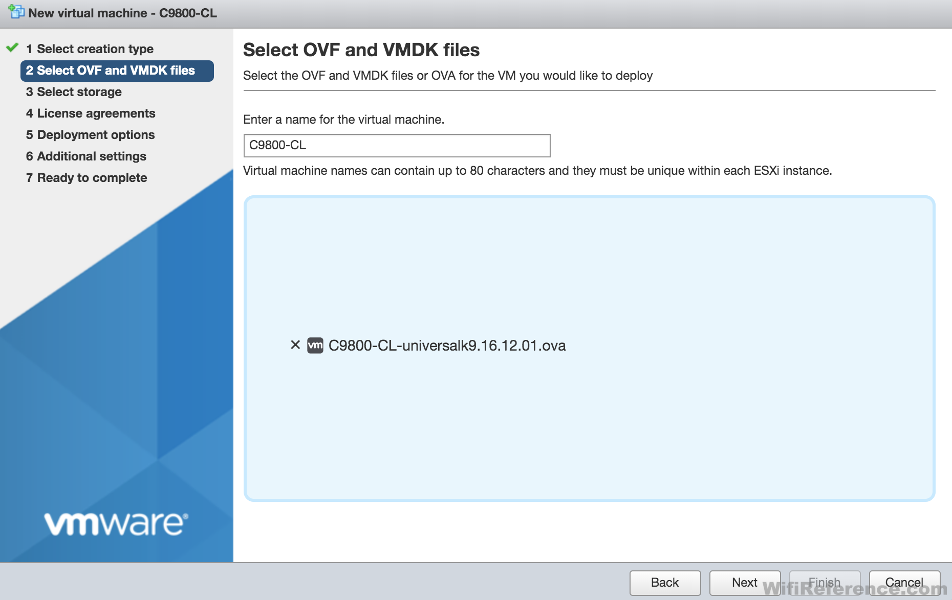
- Give the Virtual Machine a name, and select the OVA file
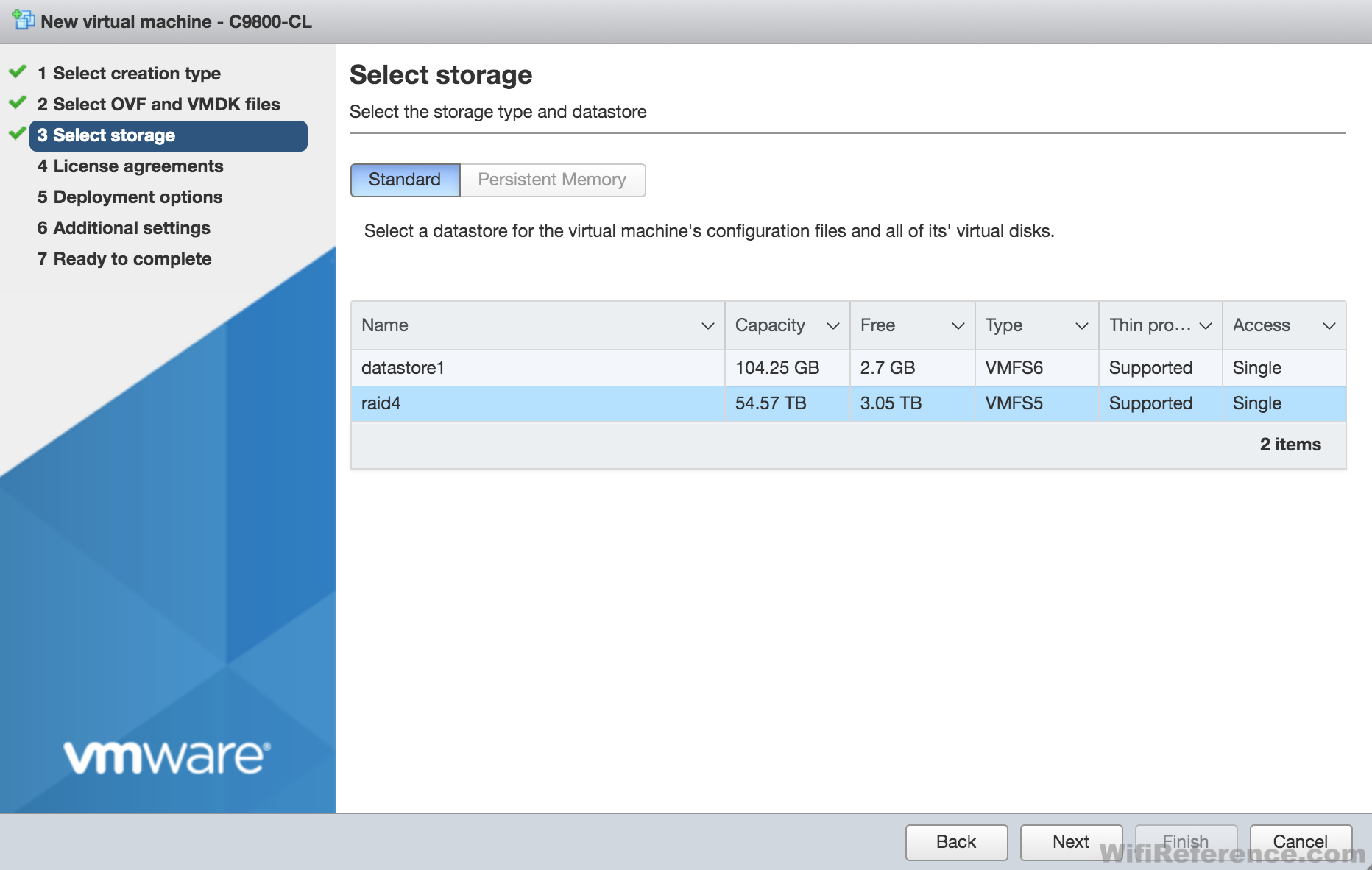
- Select the Datastore where you want to store the VM
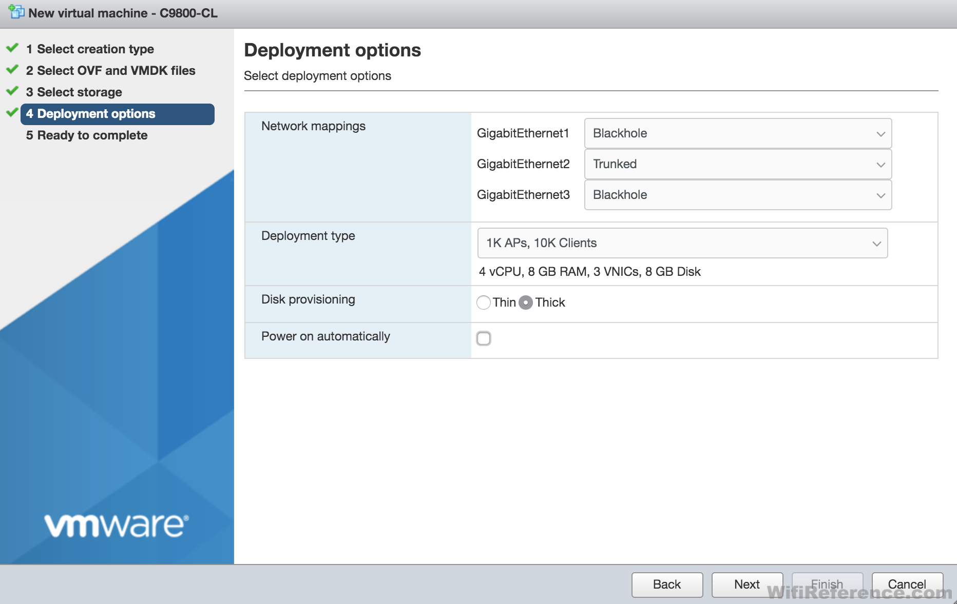
- Select the Deployment Options (Network Mappings, Scale, Disk Provisioning, etc.). Uncheck “Power on Automatically.”
Important Note: If you skipped over the networking section above, please go back and read it!
You will not be able to delete the unnecessary interfaces at this stage. We will do that after the OVA is deployed (before it is powered on for the first time). - Make sure you did NOT check the “Power on Automatically” option in the previous step.
- Click Finish and wait for the OVA to completely deploy by checking the Tasks section at the bottom of the screen and wait for it to get to 100%.
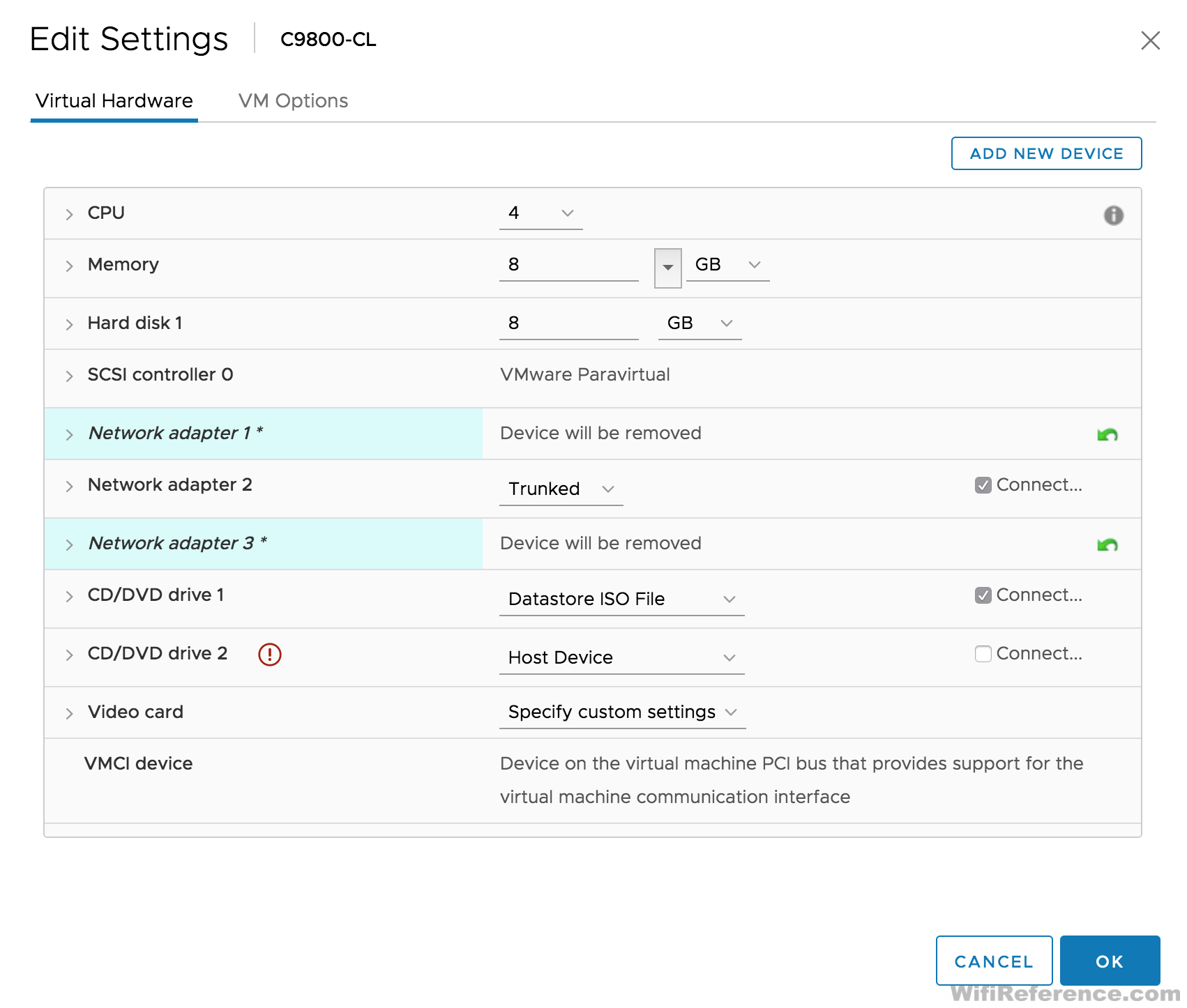
- Once it is completely deployed, you can now edit the settings to remove the unnecessary network interfaces. Right-click on the newly created VM and choose “Edit Settings.” Delete interfaces Gigabit1 and Gigabit3. (Ignore the warnings in this screenshot; they are there because my host is managed with vCenter.)
- The VM is now ready to be powered on.
Optional Step: Create a network serial port so that you can access the WLC Console via a telnet client
If you would like to be able to access the WLC console via a telnet client (instead of the VMware console), you can follow these steps.
Note: If you choose to do this, you will not be able to access the console in VMware unless you configure the WLC to use the VMware console again.
- Ensure the VM is powered off
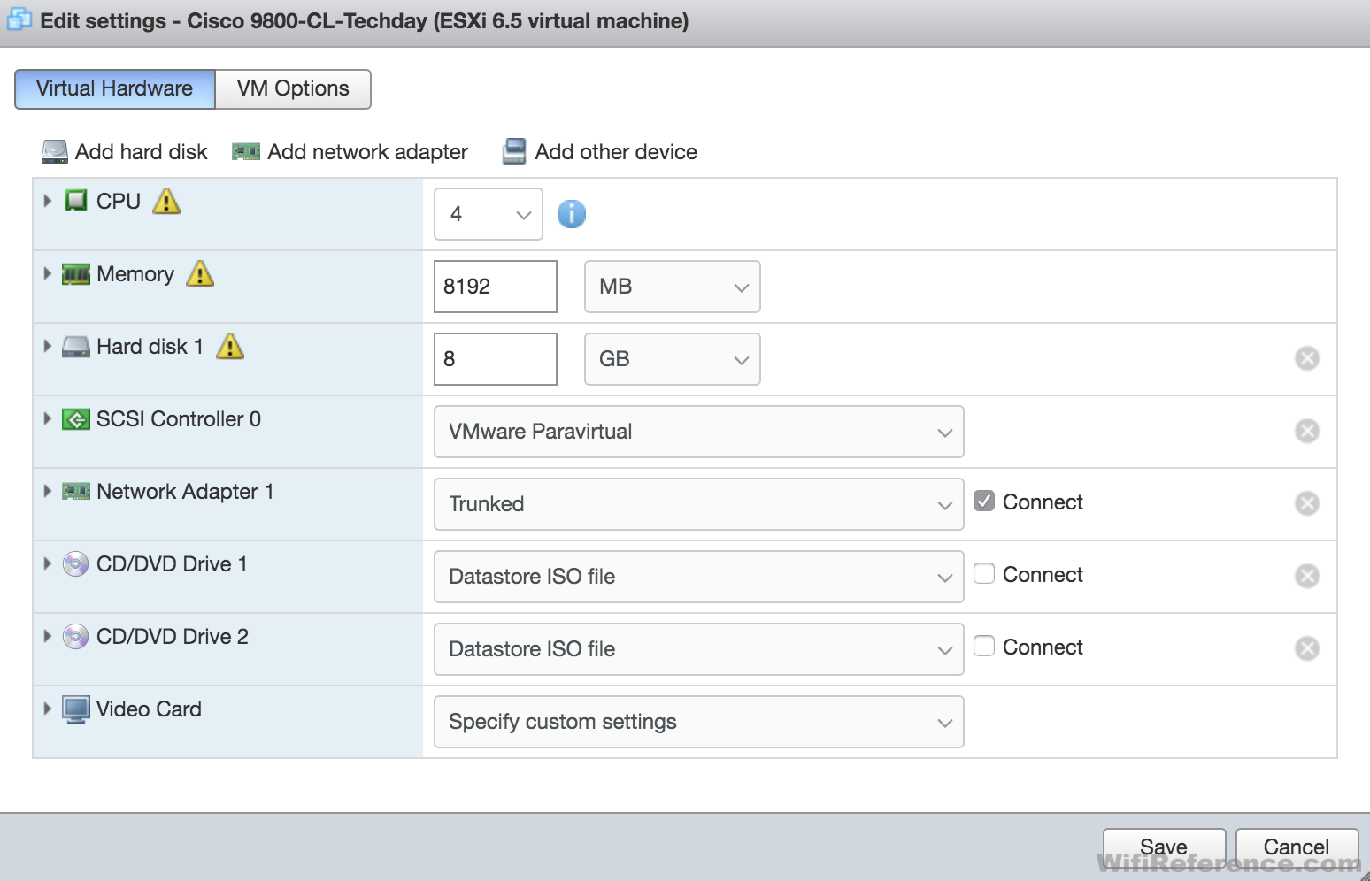
- Edit the VM settings
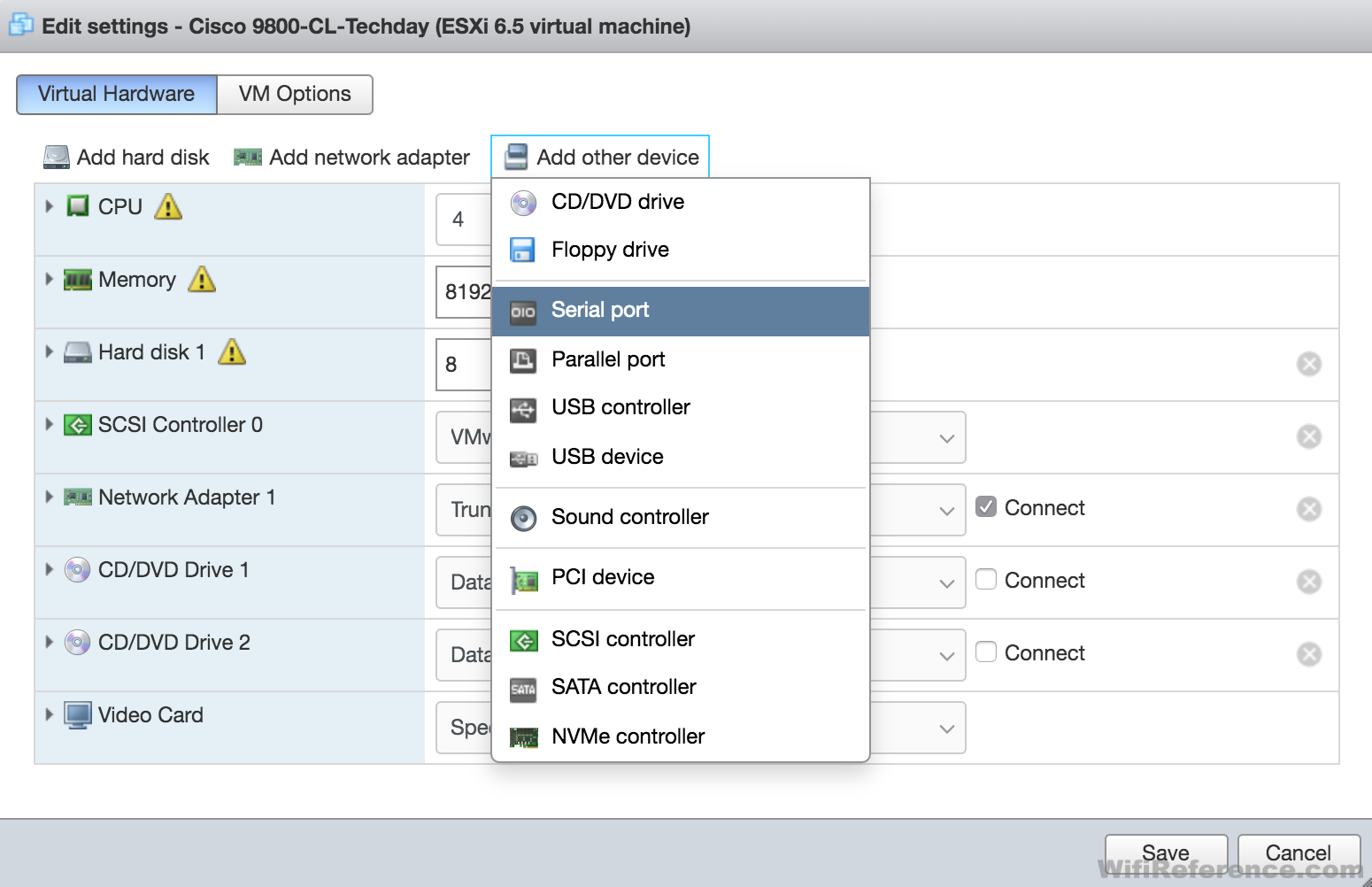
- Click “Add other device” near the top and choose Serial port
- Change the Serial port type to “Use Network”
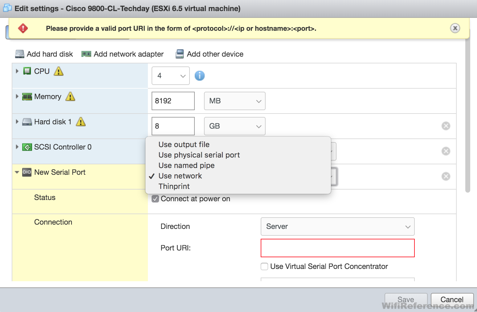
- Ensure the Direction is “Server” and then define the Port URI. Note: the URI must include the IP of your VM host (not the WLC). The port you will use should be something unique (something above 10000 should be safe). For instance, if my ESXi host is 10.0.0.9 and I wanted to use port 10001, the Port URI would look like this: telnet://10.0.0.9:10001
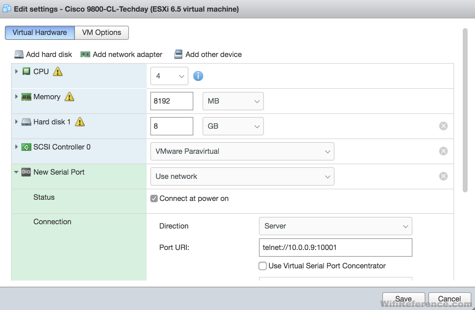
- Click Save.
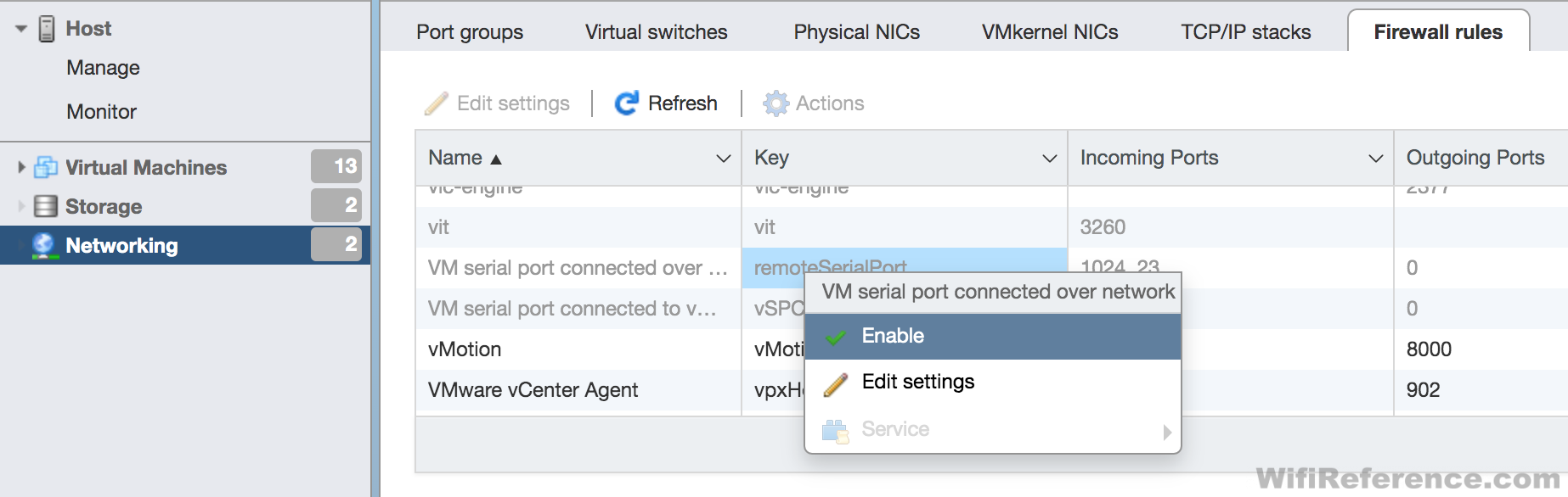
- Now you must enable the firewall rule that allows this traffic to the host. Click the Networking section on the left side of the screen and then choose the “Firewall Rules” tab at the top
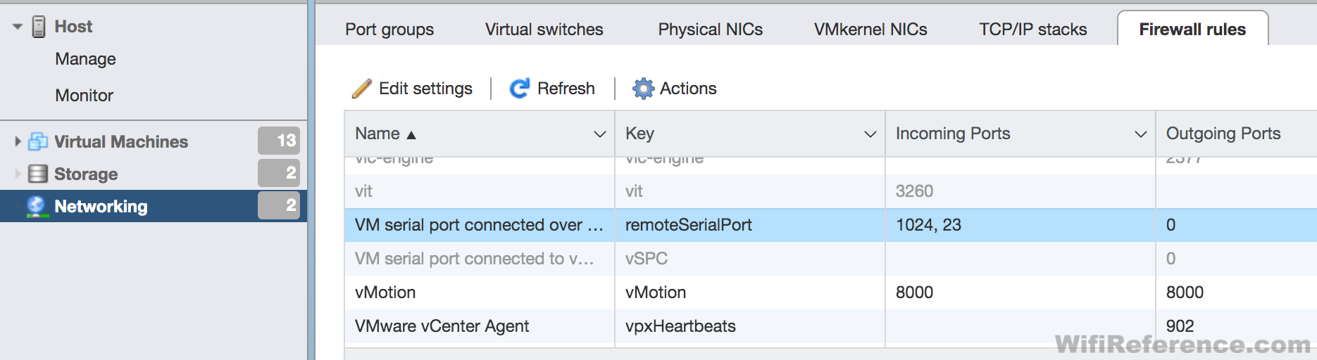
- Scroll until you see the “VM serial port connected over network” rule. Right-click on the rule and enable it.
- Once the VM is configured to send the console information to the serial port, you will be able to Telnet to your VM host on port 10001 (or whatever port you chose above) and see the console output of the WLC. There are two ways to configure the VM to send its console to the serial port.
- When you first power on the VM, there is a menu that allows you to choose between VGA and Serial console.
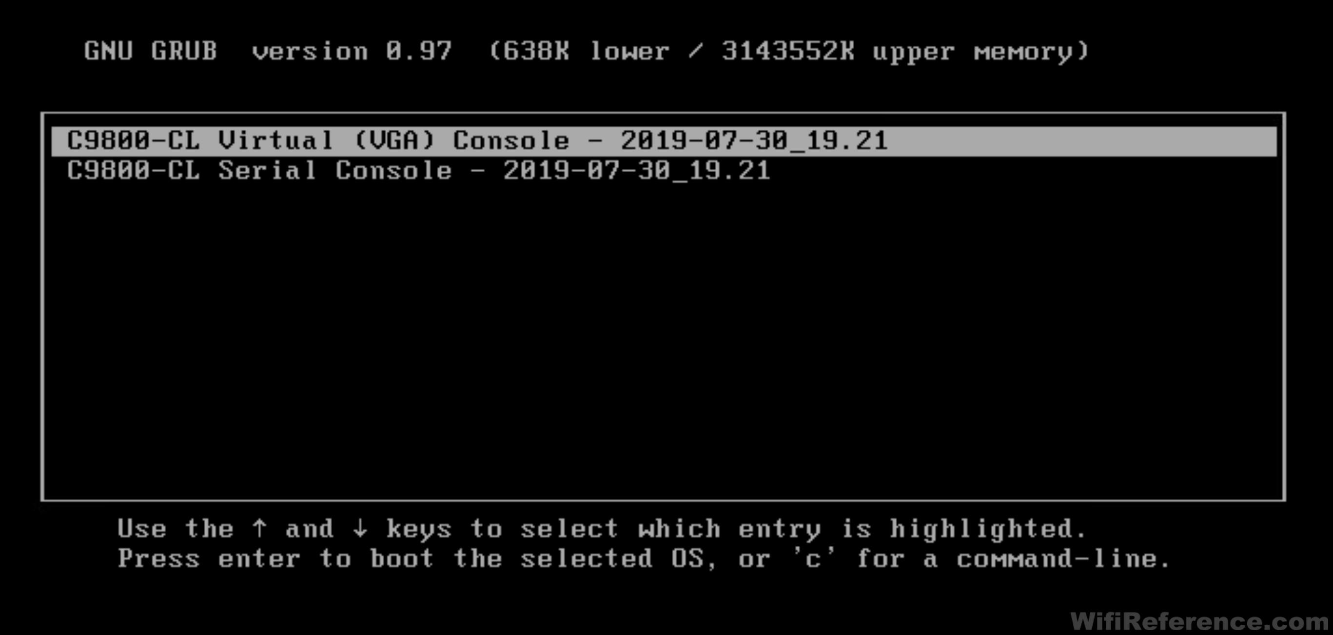
- Configure the console in the CLI with the following command (in config mode):
platform console [serial/virtual]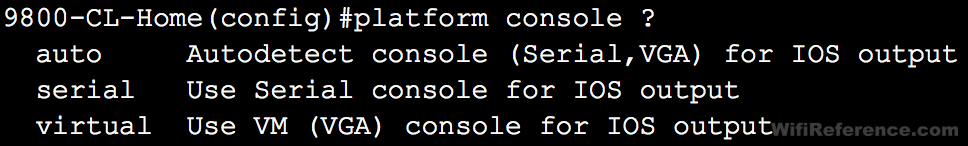
Note: I have not tried “auto.” I don’t know if it works or not.
- When you first power on the VM, there is a menu that allows you to choose between VGA and Serial console.
Deploying the Catalyst 9800-CL with vCenter 6.7
Deploying the 9800-CL with vCenter is similar to ESXi, but there are some notable differences. The OVA wizard is much more detailed and will pre-configure many of the settings in the 9800. In my opinion, this is both good and bad.
- The good: The wizard does a good job of getting the necessary information in order to make the Catalyst 9800 network accessible (for further configuration via the GUI).
- The bad (1): Some of the configuration changes it makes are not compatible with a single-interface deployment
- The bad (2): The information you enter in to the OVA deployment wizard is permanent (in a way). You can change anything you want within the configuration of the 9800 once it’s powered on, and it will save the new configuration. However, if you erase the startup-config of the 9800, it will revert back to the settings that you defined in the OVA deployment wizard in vCenter. This is particularly problematic if you set a temporary password when deploying it in vCenter. You will need to document what that password is, so that you will be able to login to the controller if you ever erase the configuration.
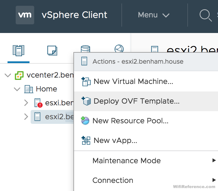
- In vCenter, right-click on the Host and choose Deploy OVF Template
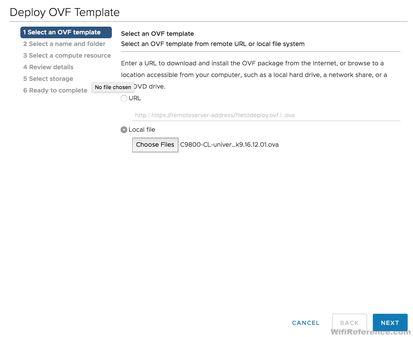
- Select the OVA file
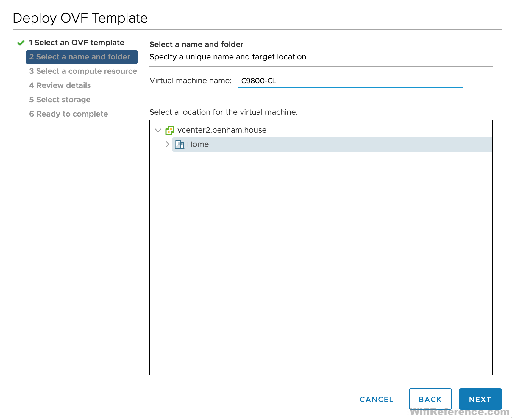
- Give the VM a name and select the folder you want it to reside in
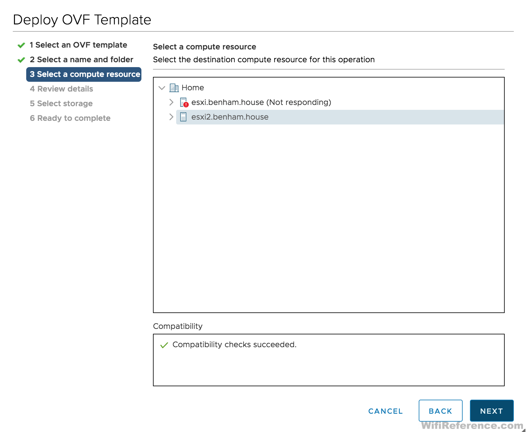
- Select the compute resource (Host) you want to deploy the VM to
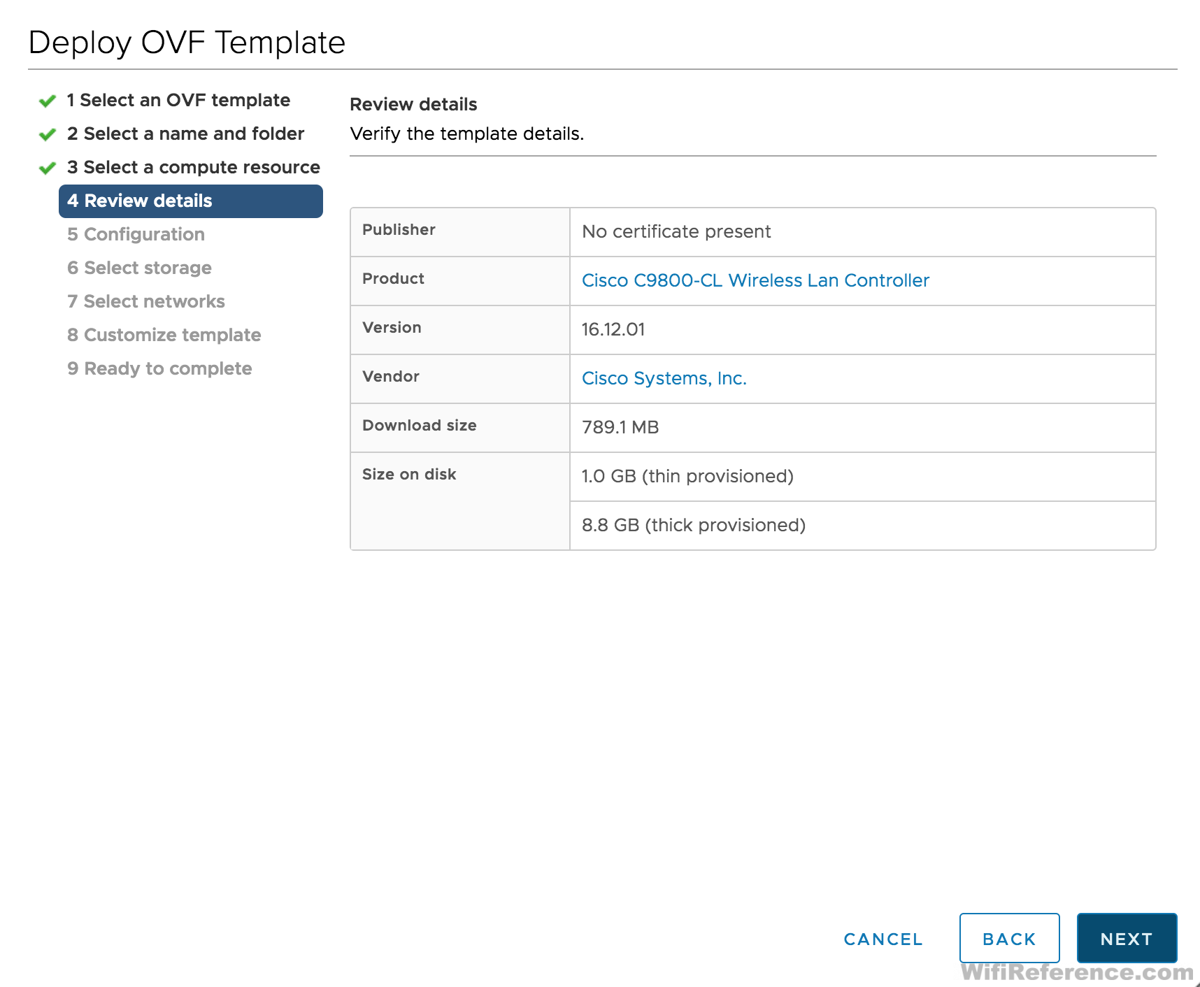
- Review the details and make sure everything is correct (there is still more to configure)
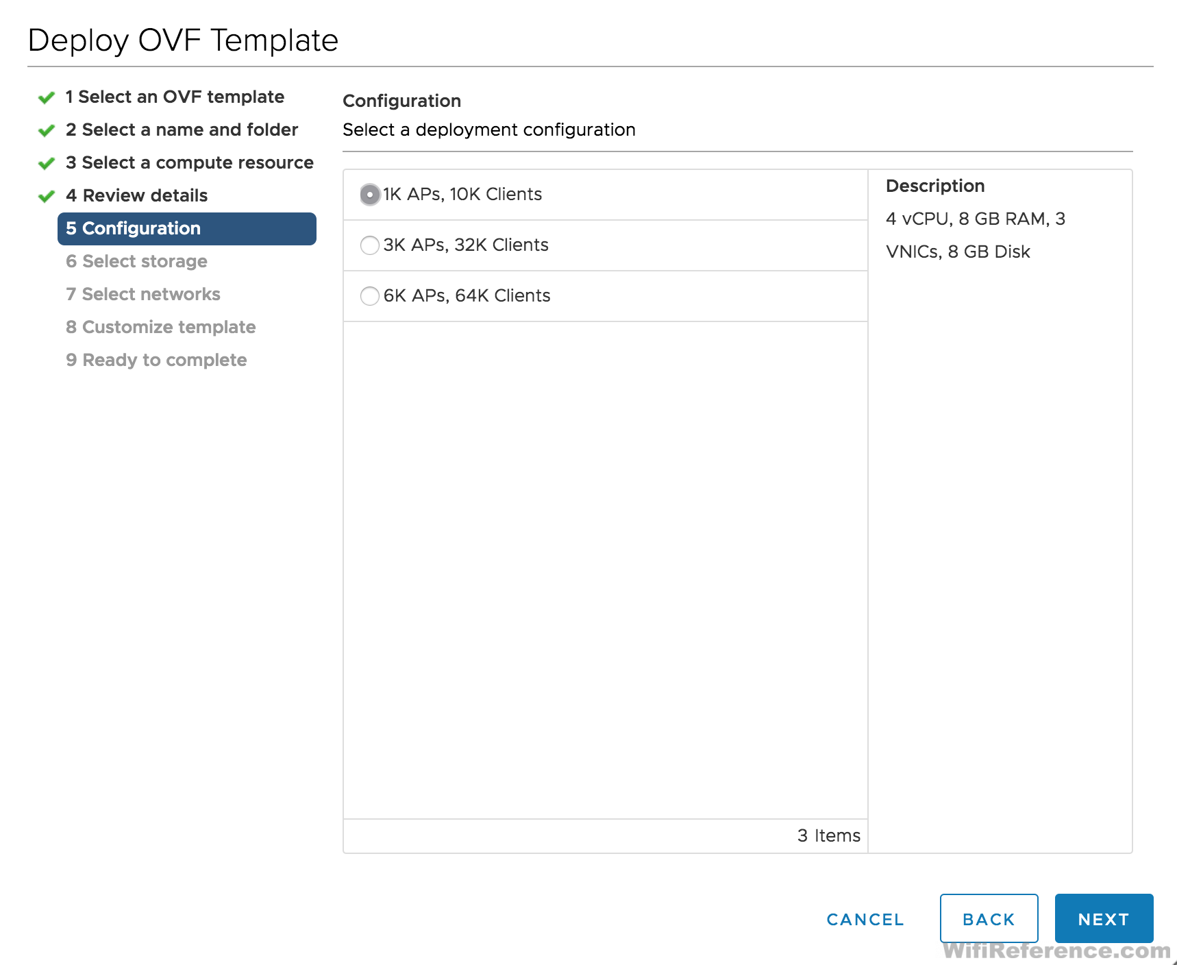
- Select the WLC Scale
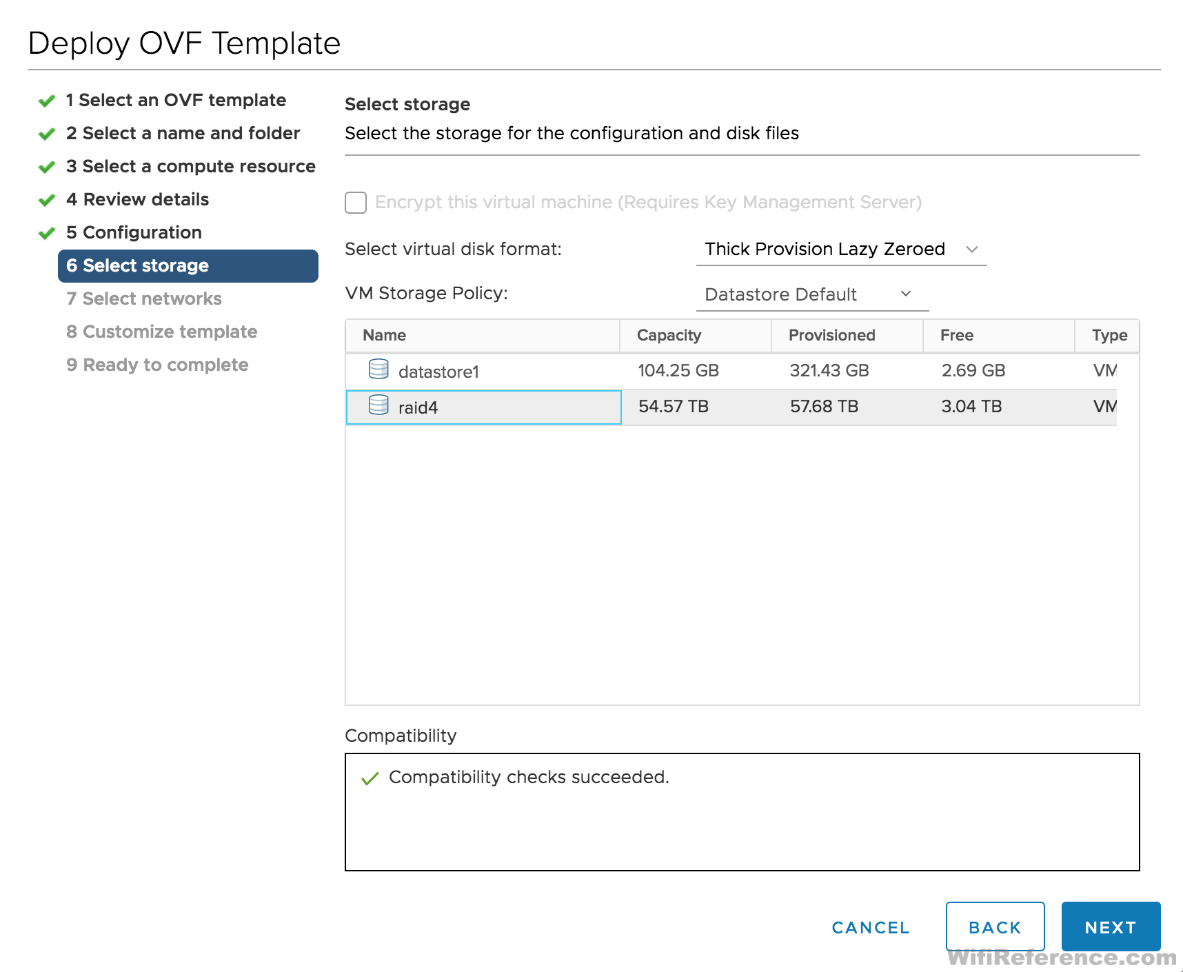
- Select the datastore you wish to deploy the VM to
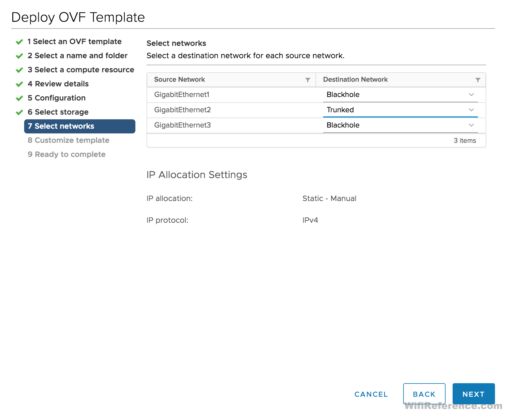
- Select the Network Mappings. Note: If you skipped the networking section above, please read it before proceeding! You cannot delete interfaces at this point; you must edit the VM after it is deployed. It doesn’t really matter what you map to Gigabit1 and Gigabit3, as long as you edit the VM settings before you power it on.
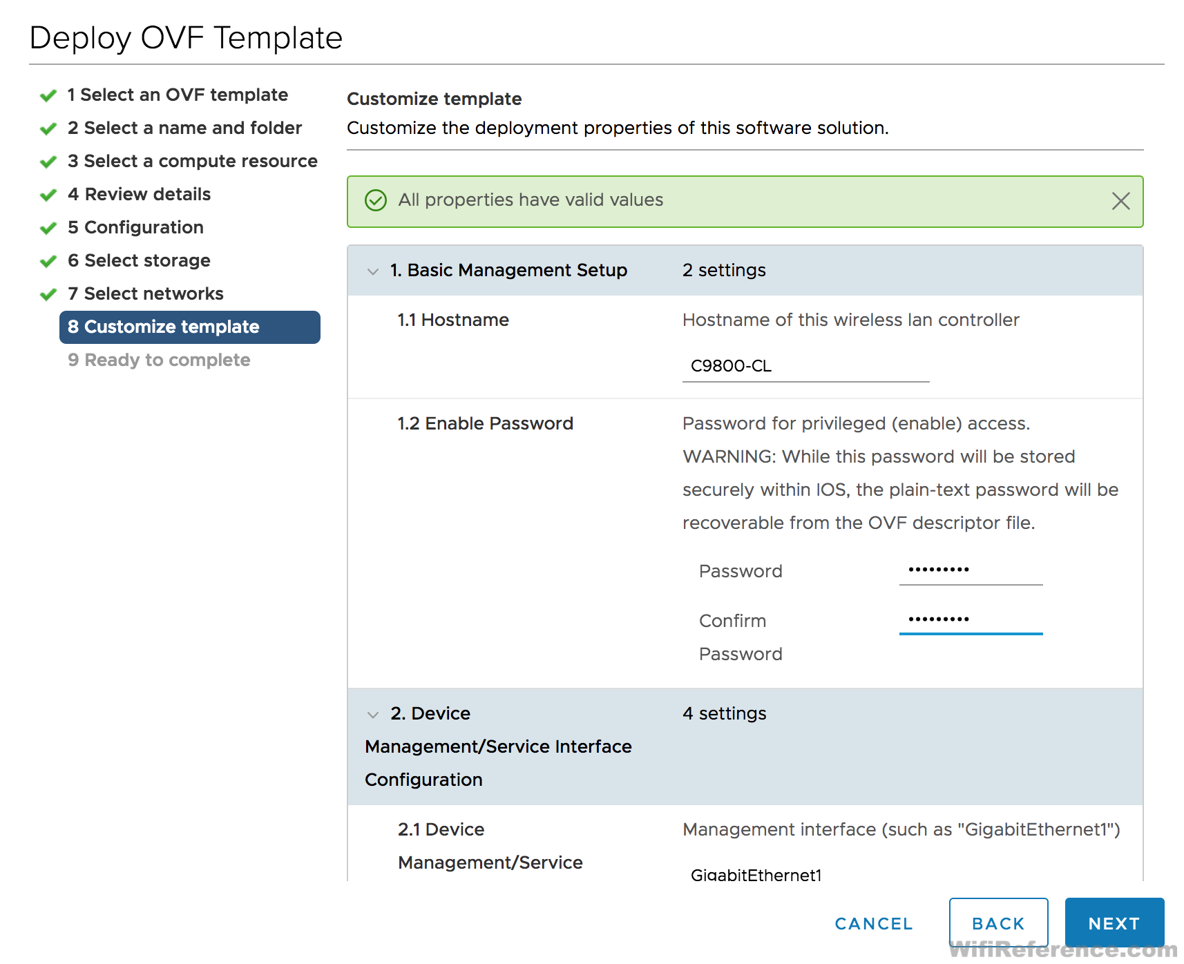
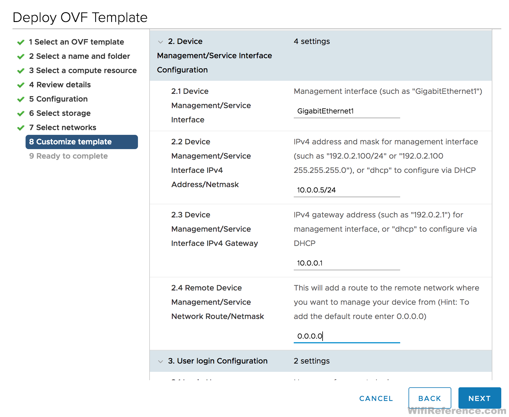
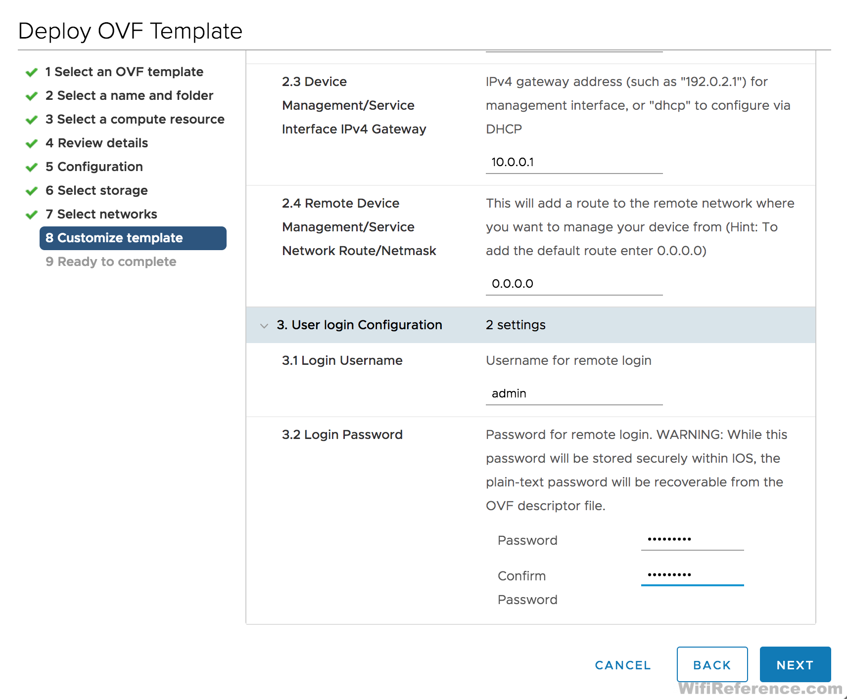
- This is where things are significantly different from ESXi. Define all of the fields in this section with appropriate values.
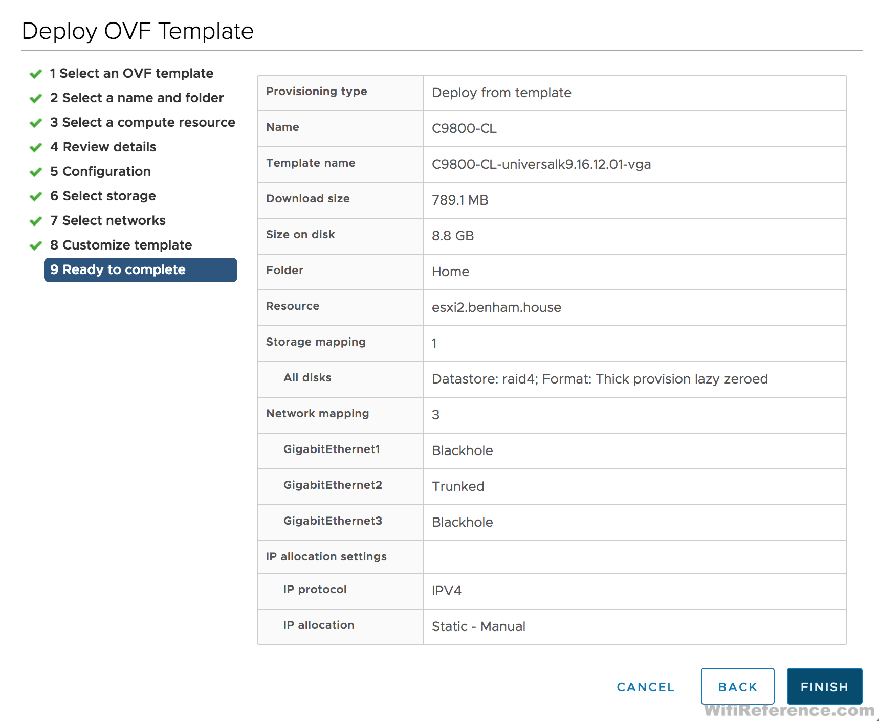
- Review all of the details. Click Finish and wait for the VM to deploy
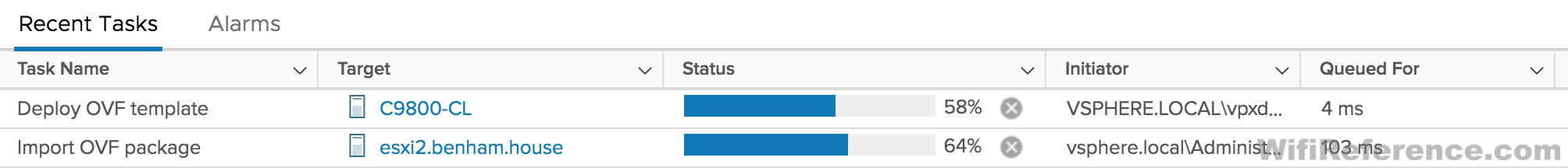
- Check the status of the VM deployment in the Recent Tasks section at the bottom of the screen. You need to wait for this to complete before proceeding.
- Right-click on the newly created VM and choose Edit Settings. We need to delete the unused interfaces. In this case, we will be deleting Gigabit1 and Gigabit3.
- Power on the VM and open the console. Proceed to the “Configuring the Catalyst 9800-CL when deployed from vCenter” section below.
Deploying the Catalyst 9800-CL with OVFTool
If you can’t deploy the VM with ESXi, and you don’t have vCenter, your best option is OVFTool. OVFTool (download it from that link) is a command line utility that allows you to import and export OVF/OVA packages on many VMware platforms. In this case, it allows the OVA to be deployed on VMware versions that aren’t officially supported by Cisco, or in situations where you are encountering errors. Here is an example of the syntax I’ve used with the Catalyst 9800:
ovftool -dm=thin -ds=datastore1 --net:"GigabitEthernet1"="VM Network" --net:"GigabitEthernet2"="VM Network" --net:"GigabitEthernet3"="VM Network" --deploymentOption="4CPU-8GB" -n=C9800-CL-1 /Users/Dave/Downloads/C9800-CL-universalk9.16.12.01.ova vi://10.0.0.9
You will need to make several changes to the command line syntax to make it appropriate for your environment. Also, this command structure is very specific. Make sure you don’t have any extra characters, missing spaces, etc. when you enter the command.
- -dm=[thin/thick] – Whether you want thin or thick disk provisioning
- -ds=[datastore] – The datastore name that you want the VM deployed to. This is case sensitive.
- –net:”GigabitEthernet1″=[port group] – The name of the port group you want this NIC bound to.
- –net:”GigabitEthernet2″=[port group] – The name of the port group you want this NIC bound to.
- –net:”GigabitEthernet3″=[port group] – The name of the port group you want this NIC bound to.
- –deploymentOption=[scale] This refers to the scale of the VM you want to deploy. Refer to the deployment guide if you want to deploy the 3K or 6K AP version. The syntax above is for the 1K AP (smallest) version.
- -n=[VM Name] This will become the name of the VM in VMware. If it will have spaces, you must surround it in quotes.
- Full path to the OVA file
- vi://[IP address of the ESXi host]
Be sure to read the Networking section above, and delete the unnecessary interfaces before powering on the VM.
Configuring the Catalyst 9800-CL when deployed from ESXi or OVFTool
Note: There are actually some significant differences in the configuration process, depending on whether you deployed the OVA with ESXi/OVFTool or vCenter
In this example, I will be using the following criteria for configuring the Catalyst 9800-CL:
- Interface configuration: Single, Trunked
- Redundancy mode: Off
- Management VLAN: 10
- Management IP: 10.0.0.3
- Client VLAN: 20
- Client Interface IP: 10.10.10.3
Why am I not using the Web GUI Interface? Because it won’t allow you to configure the WLC without using Gigabit1 as the OOB Management Interface. Besides, you wouldn’t use the GUI to configure a switch from scratch, would you?
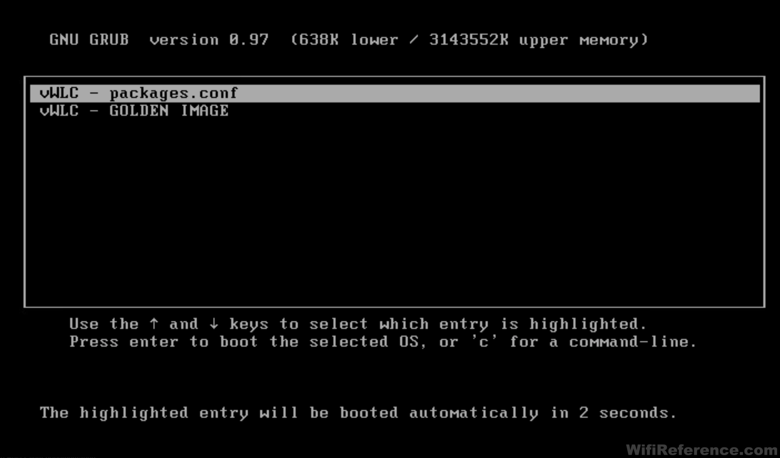
- Power on the VM and open the console.
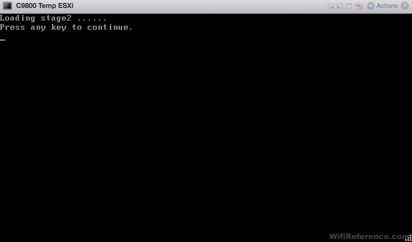
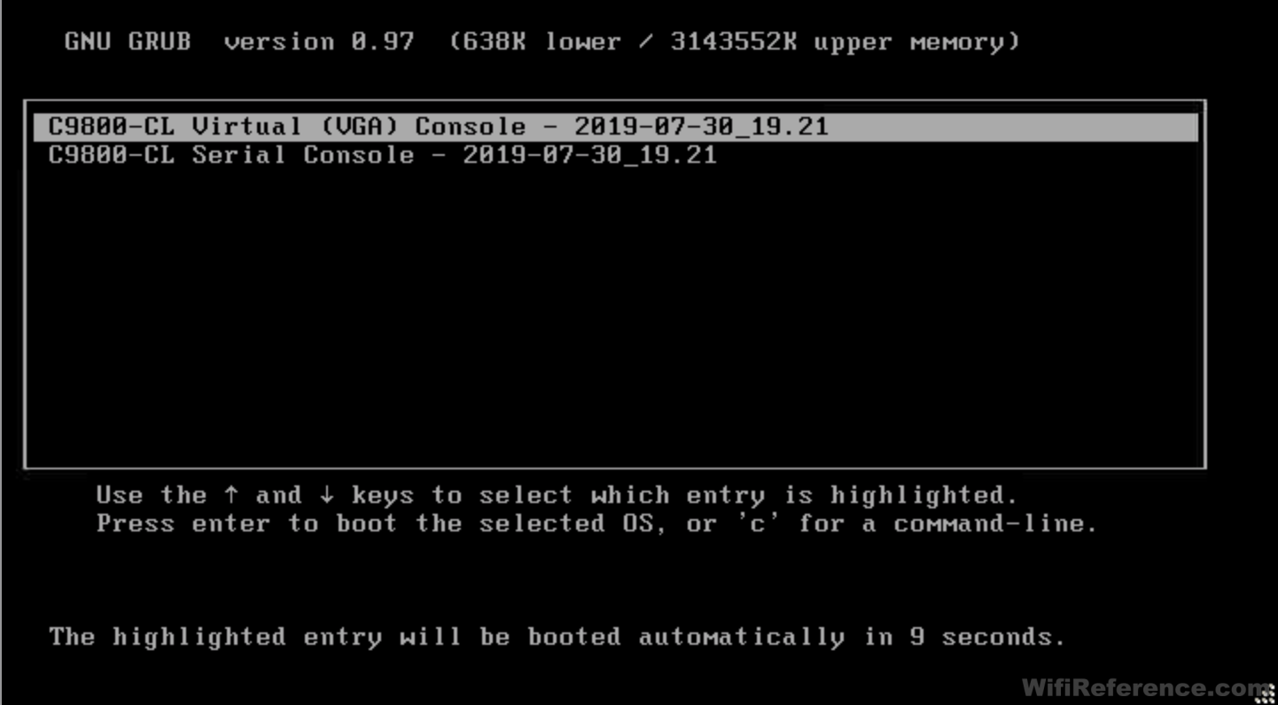
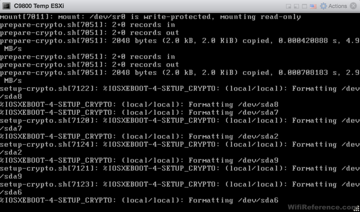
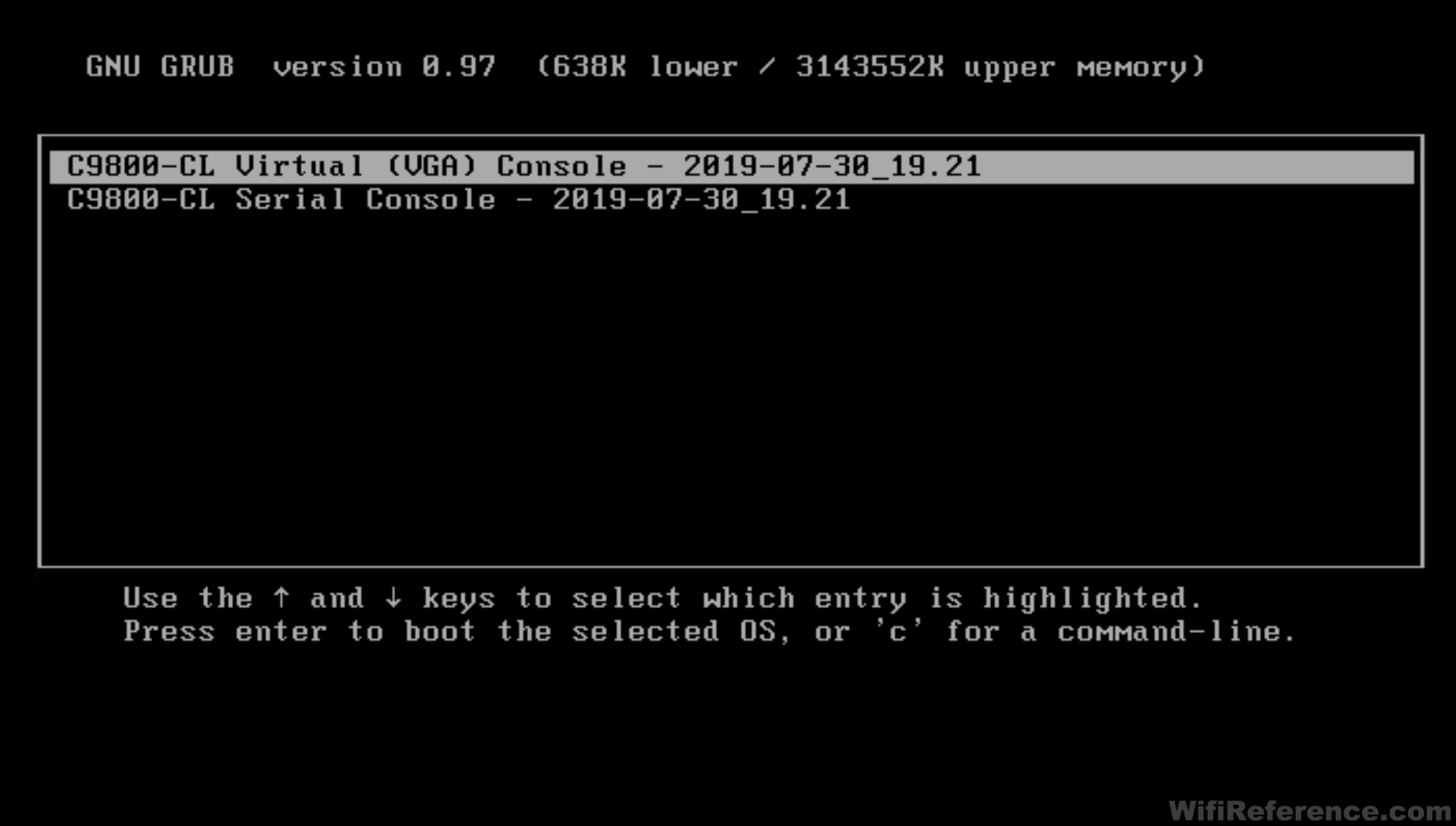
- Select your console preference in the menu. Pay attention to the console right away, because if you want to redirect the console to a serial port (see optional section above) you need to make that selection right away.
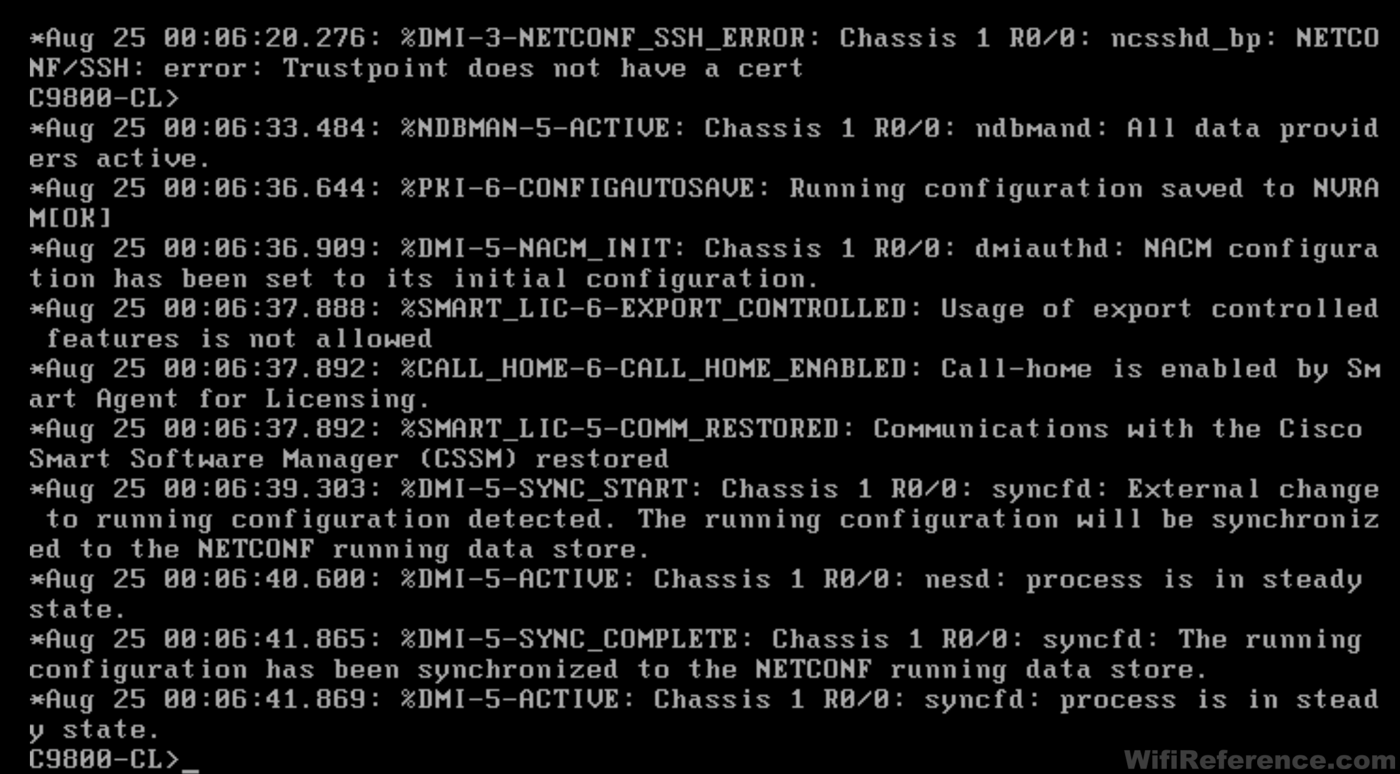
- It will take about 5 minutes for the controller to go through its initial provisioning scripts. The controller will reboot itself during this process.
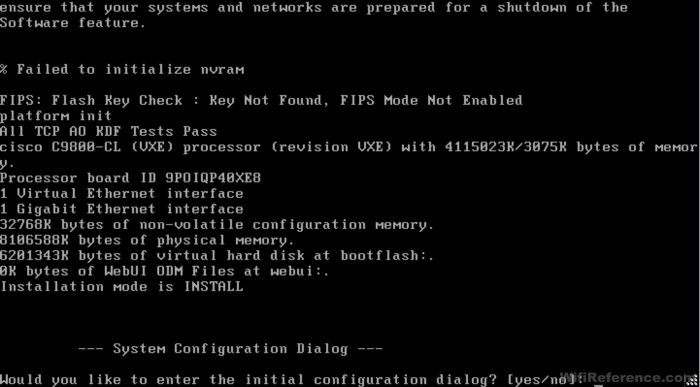
- Eventually, you will be prompted with the initial configuration dialog box. Choose no.
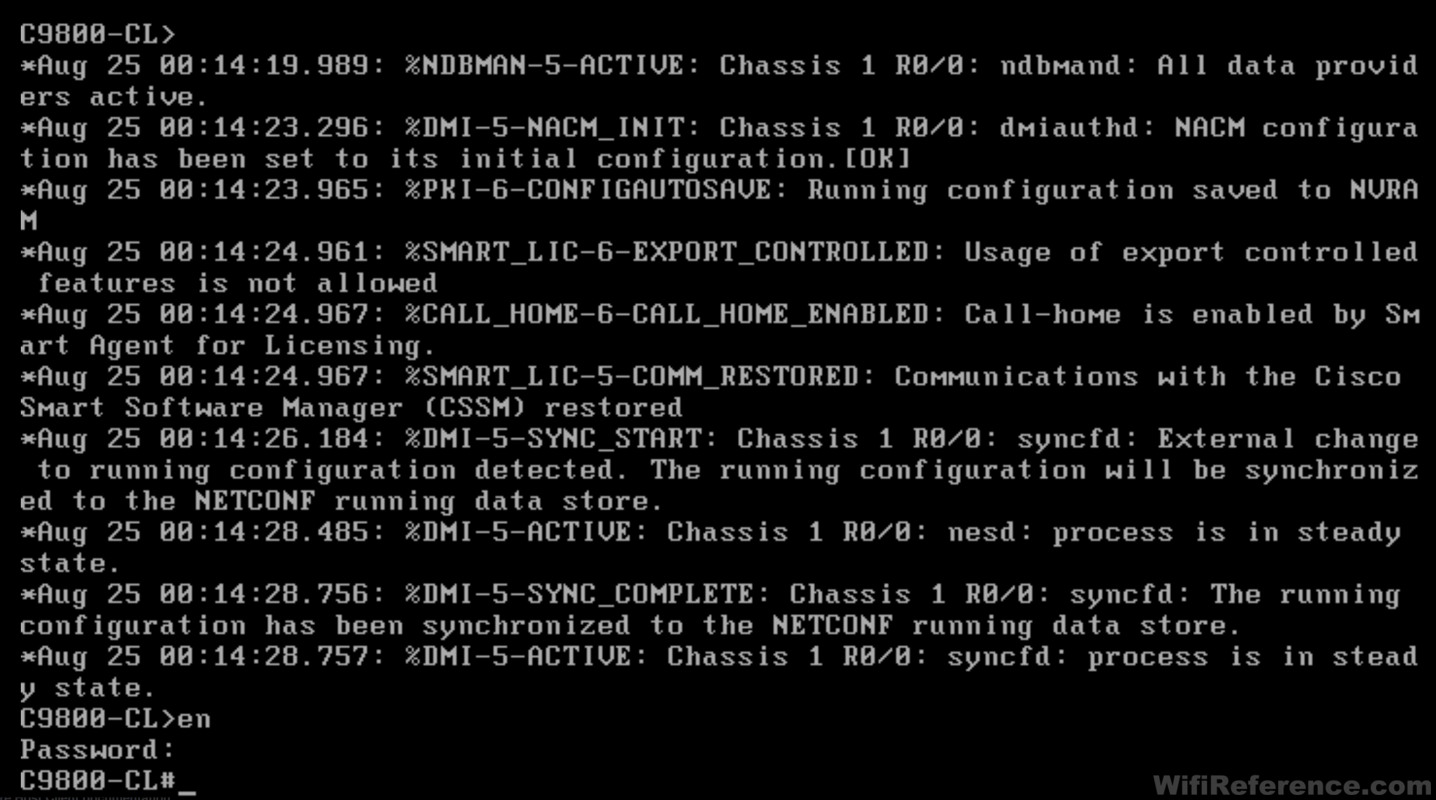
- Enter enable mode, and config mode.
Enable synchronous console logging, because there are many status messages that appear throughout this process.
Set the hostname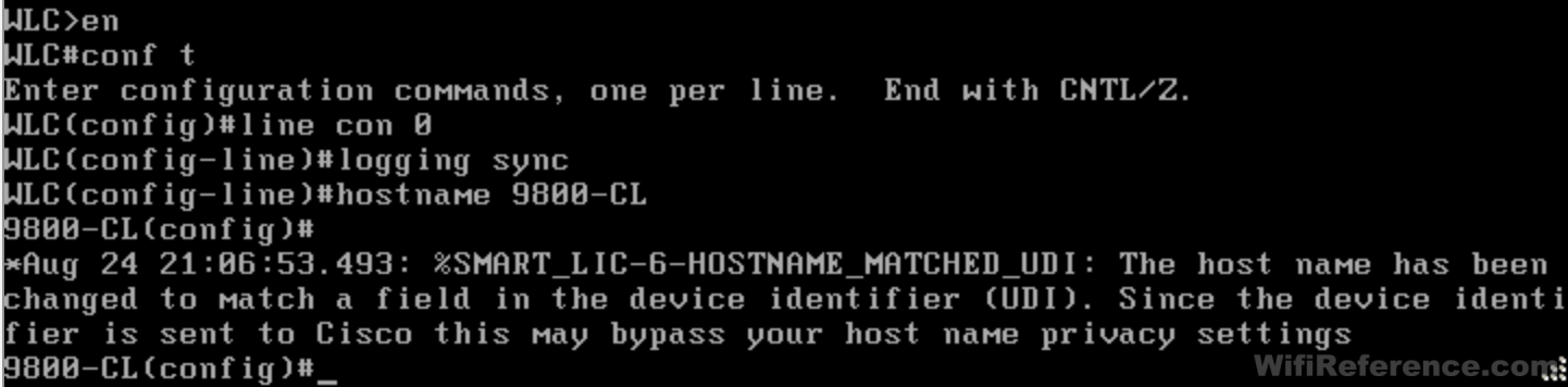
- Set VTP mode to Transparent (this is a switch, after all)
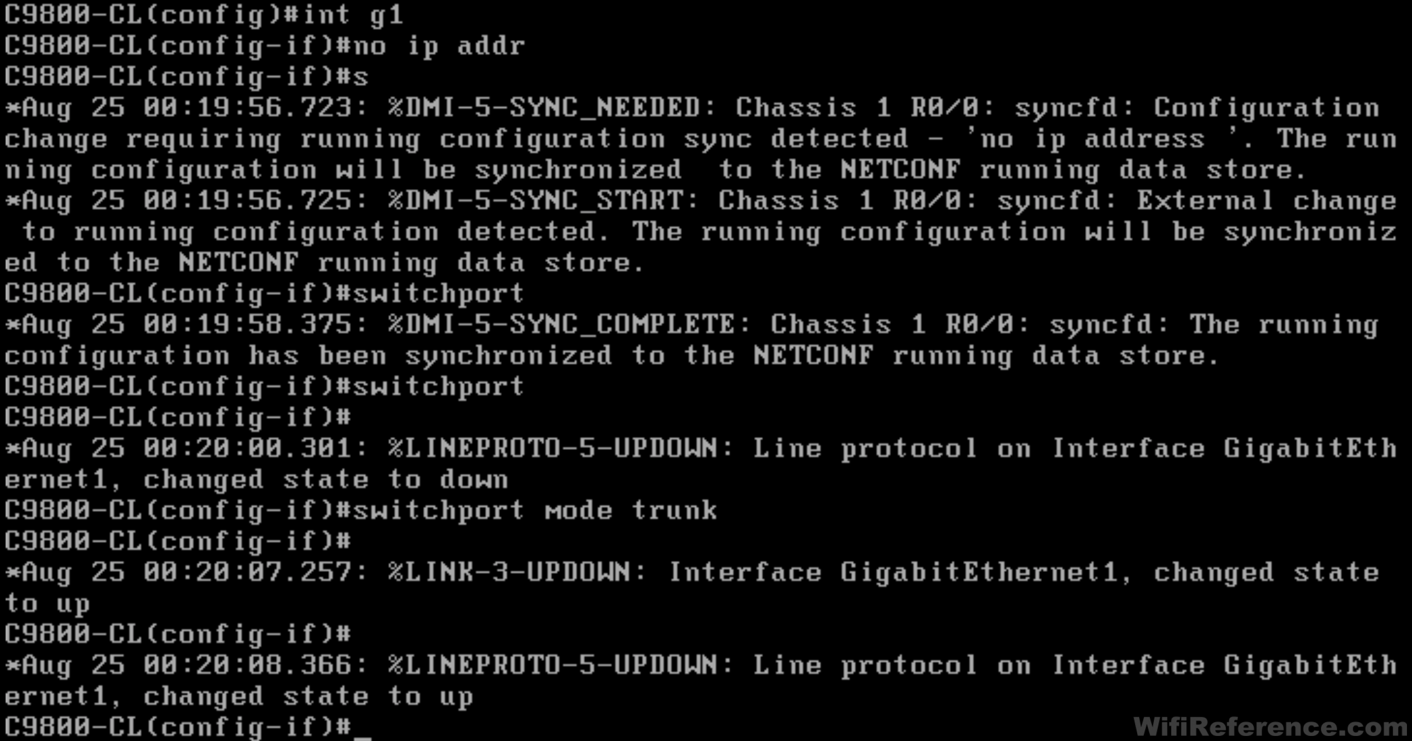
Set Interface Gigabit1 to a trunked switch port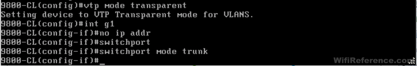
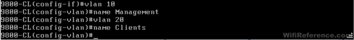
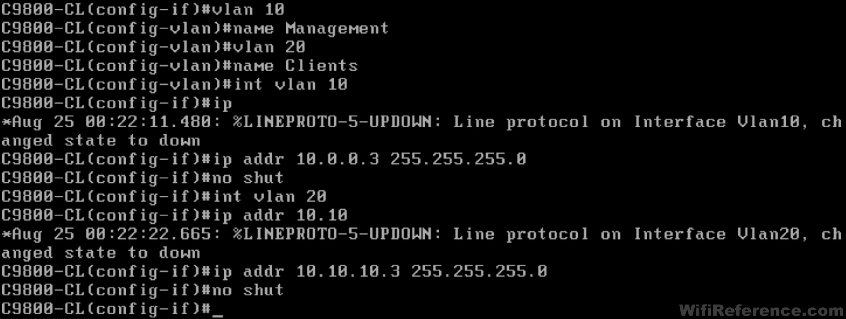
- Create your management and client VLANs
- Shut down Interface VLAN 1

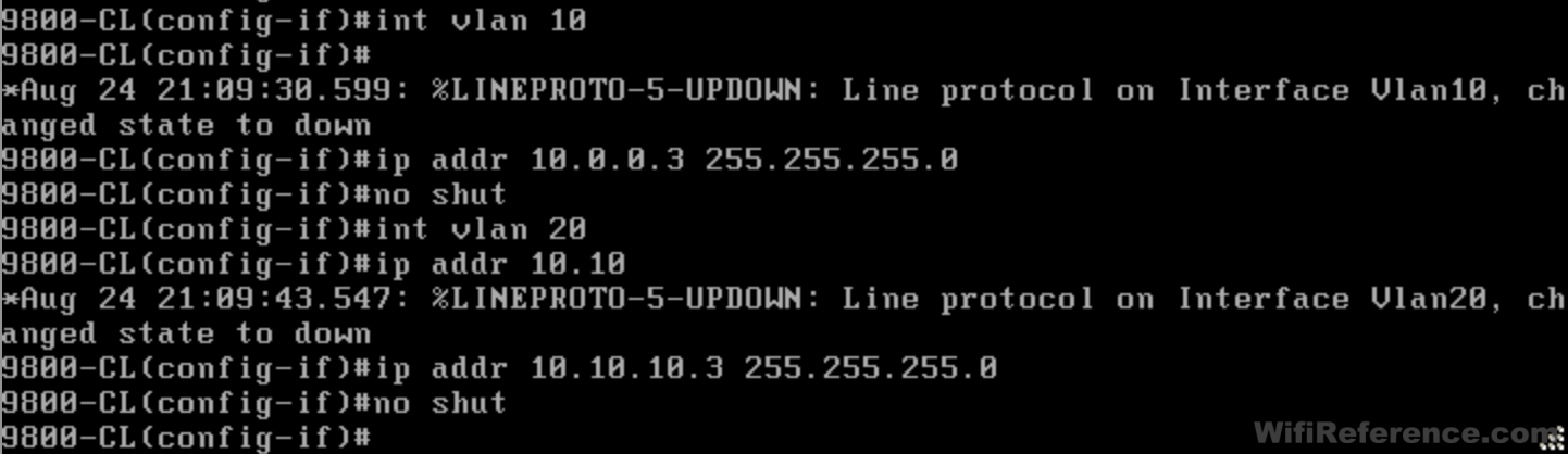
- Create Interface VLANs for Management and Clients, and configure their IP addresses
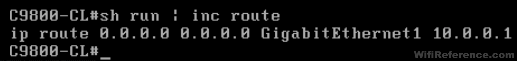
- Add the default route

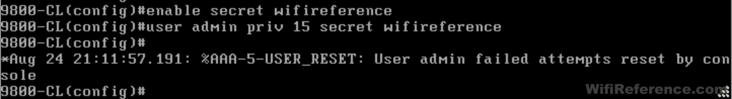
- Configure the enable secret and administrator user
- Configure local user authentication for VTY

- Configure the Wireless Management Interface and allow management via wireless (mgmt via wireless is optional)

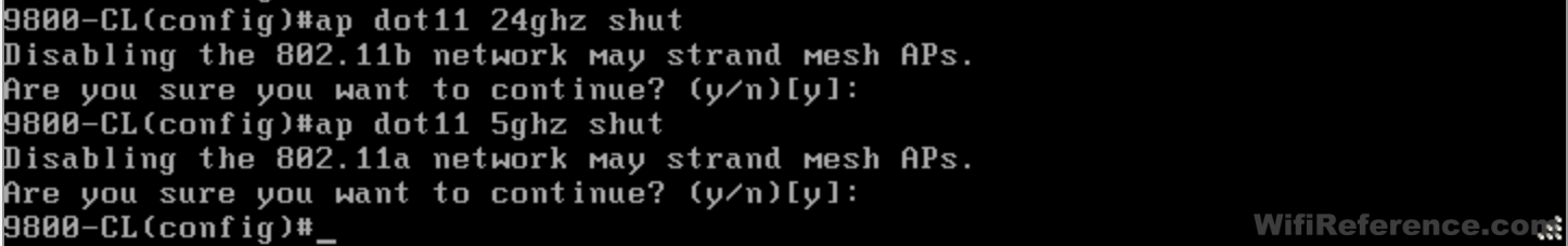
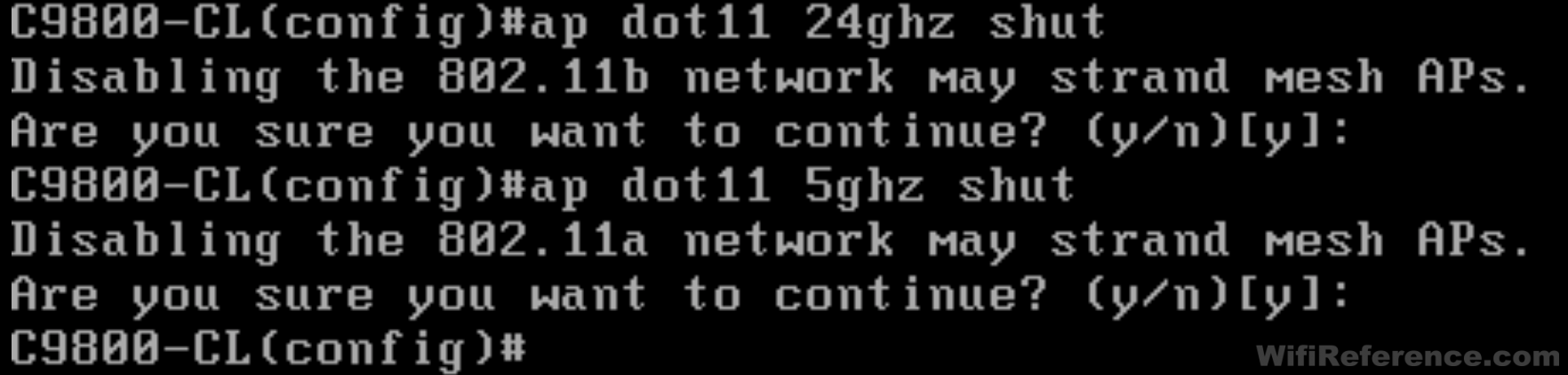
- Now we must temporarily disable the 2.4GHz and 5GHz bands in order for the next step
- Configure the AP Country Code. Note: The country code must be in ALL CAPS. Also, this is the command that will prevent the initial config dialog wizard from appearing when you launch the GUI.
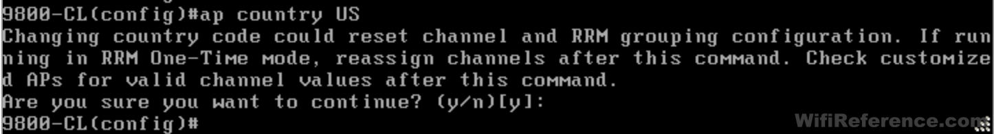
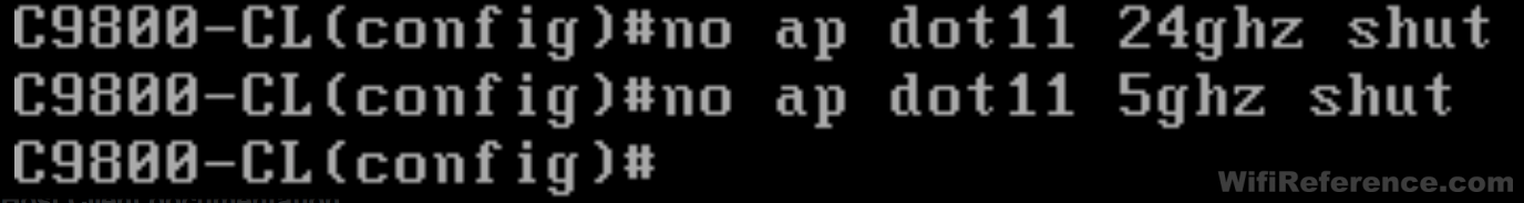
- Re-enable the 2.4GHz and 5GHz bands

- Configure the WLC to sync time with an NTP server (this is important for the certificate generation step in the future)

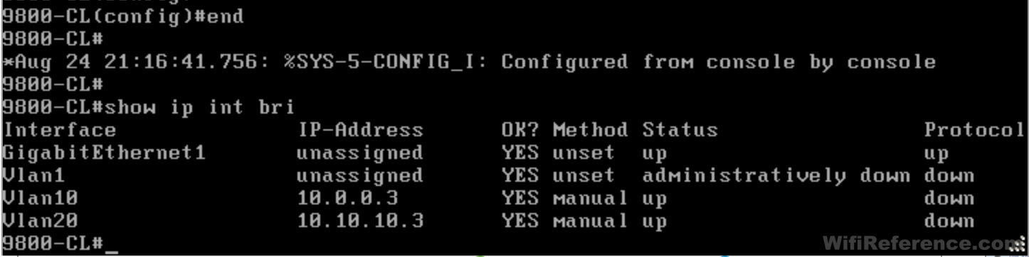
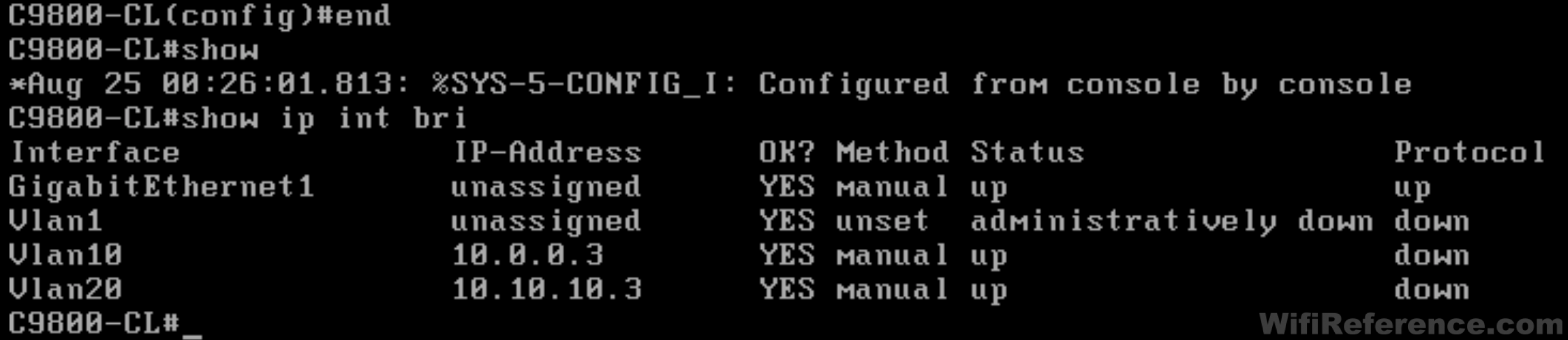
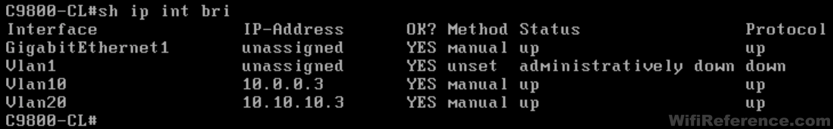
- Check the status if your Interface VLANs. Chances are, they are up/down. They will stay this way indefinitely unless you reboot or perform the next step.
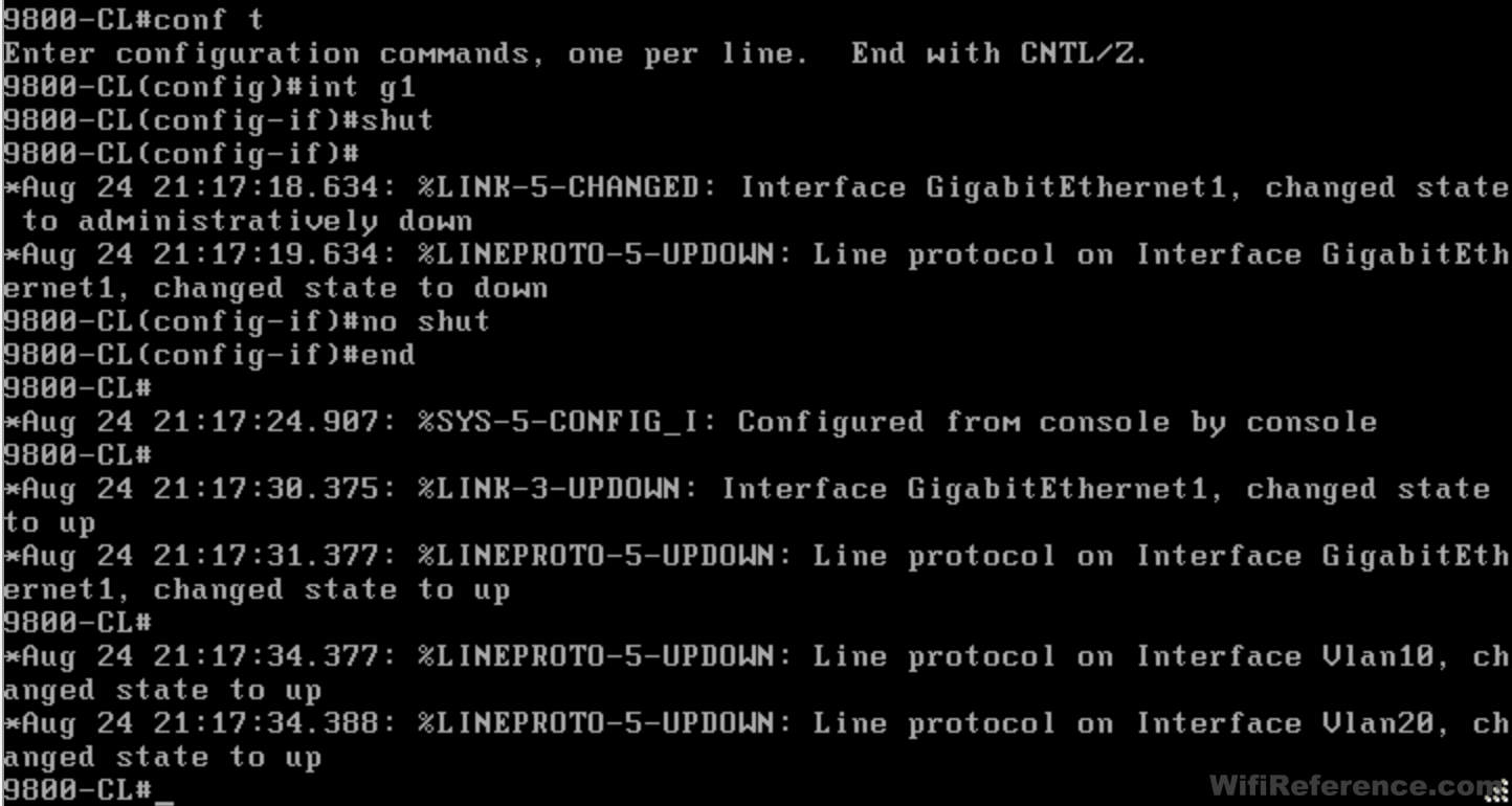
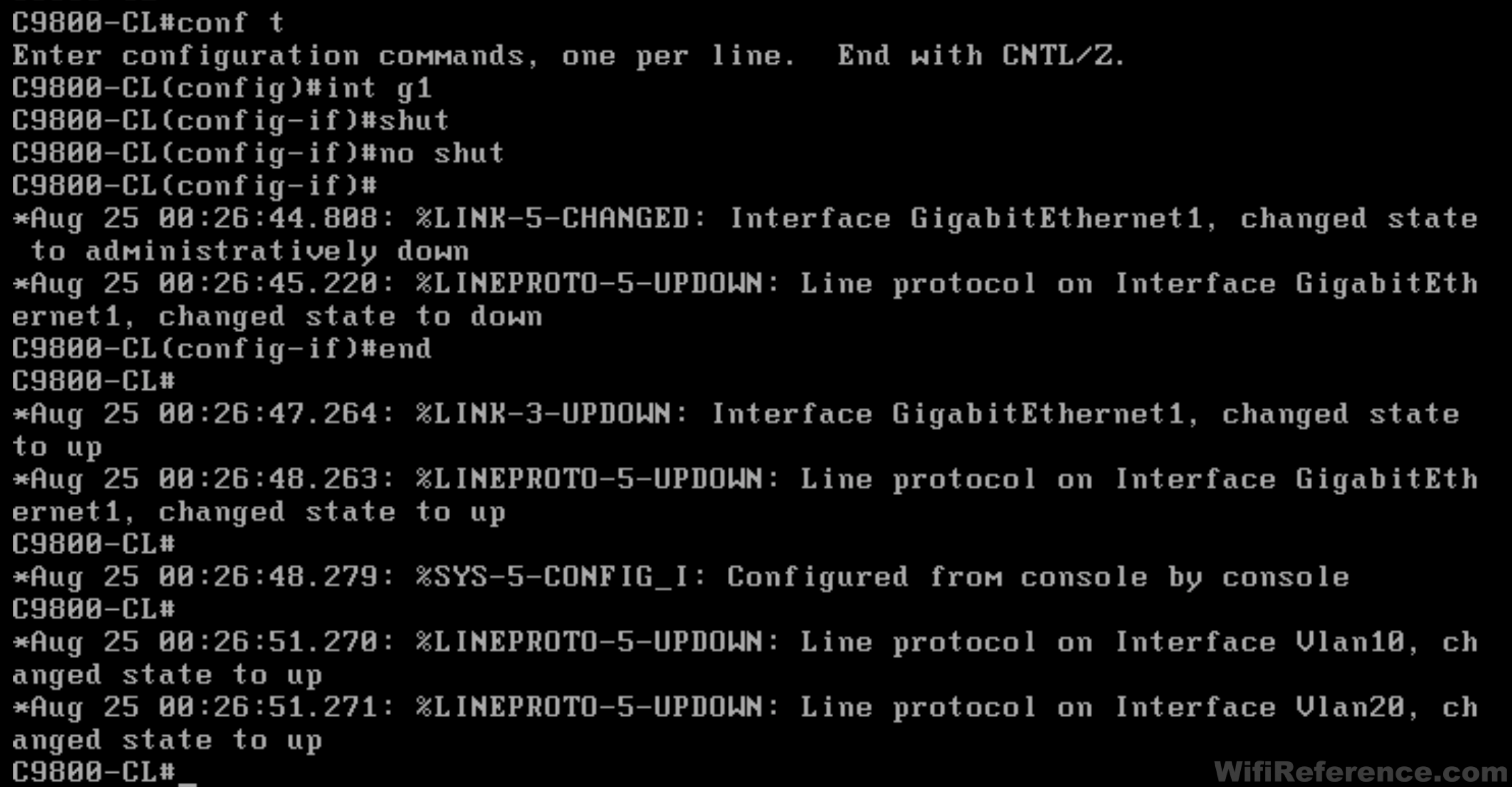
- Disable/enable Interface Gigabit1 by performing a “shut” and “no shut” on it. This will bring the Interface VLANs online.
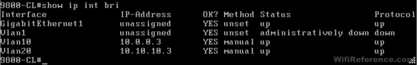
- Now verify that the Interface VLANs are up/up
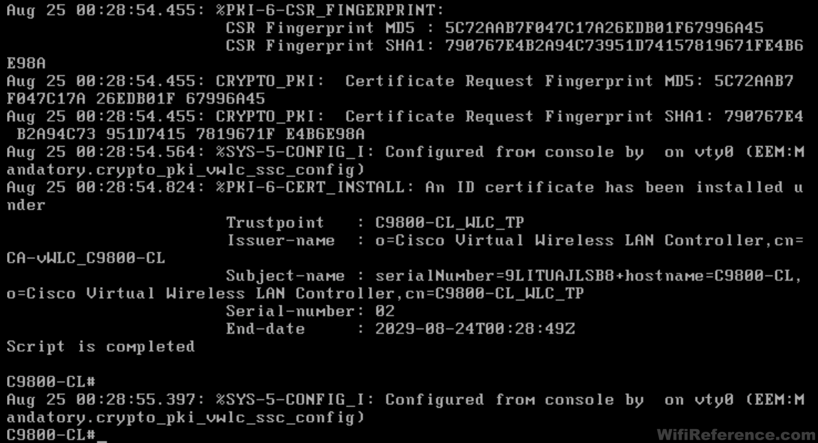
- Now we can proceed to the most important step of the configuration: Generating the Self-Signed Certificate. This certificate is used for AP communication, and APs will not join until this certificate has been created. Issue the following command (change the password at the end):
Note: This command is not entered in config mode.
wireless config vwlc-ssc key-size 2048 signature-algo sha256 password 0 <pwd>
- You should see a ton of status messages appear on the screen.
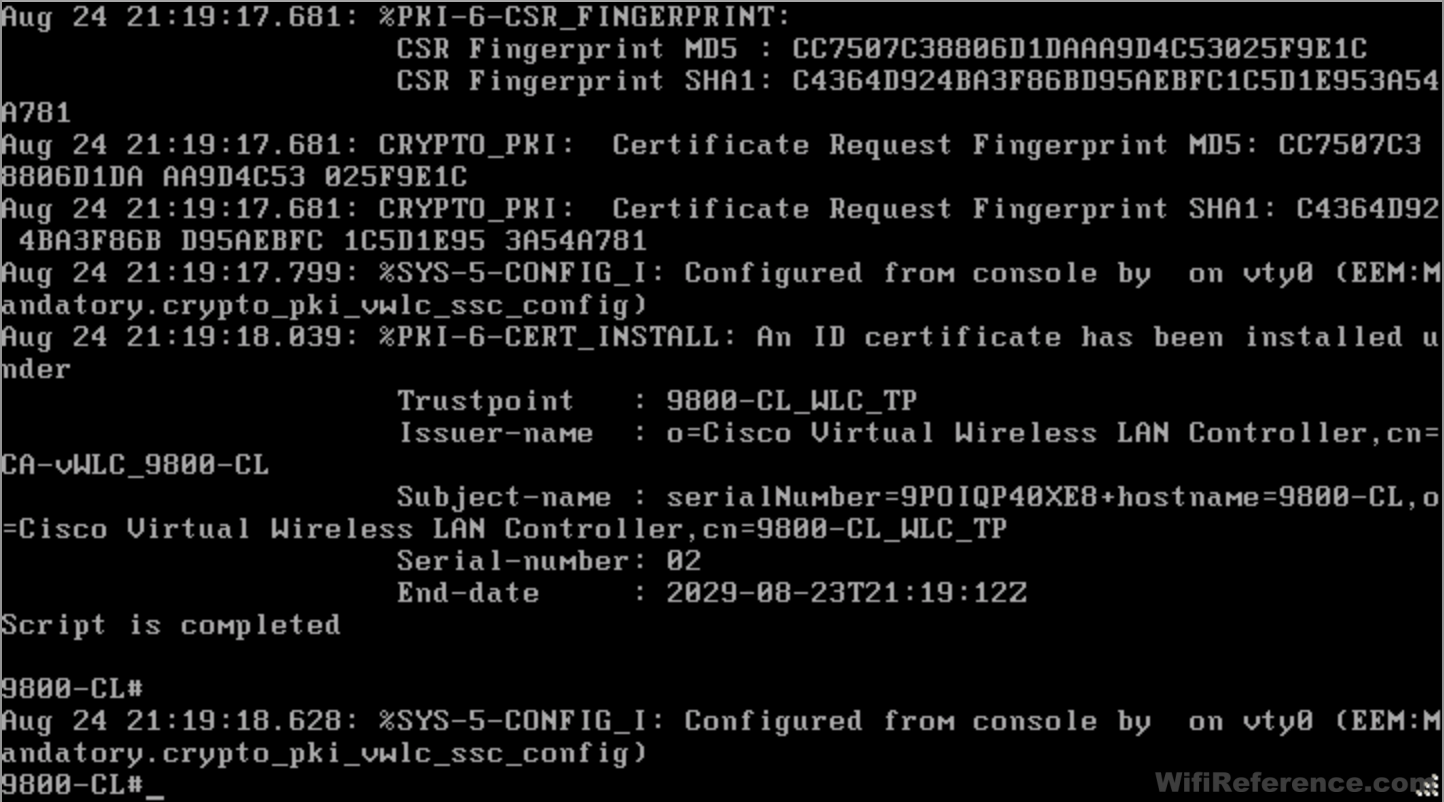
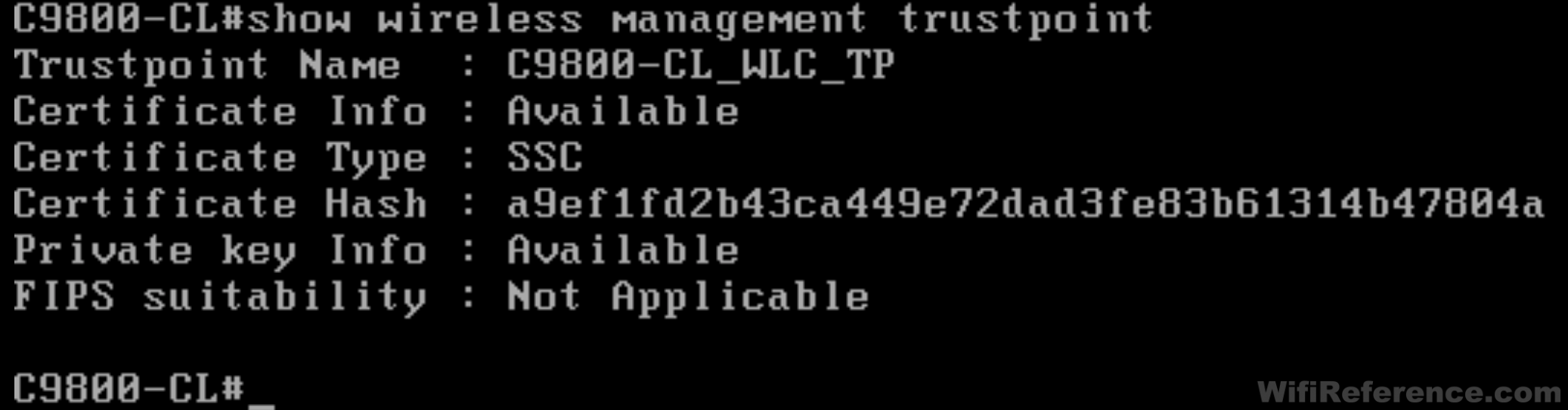
- Verify that the certificate was created by issuing the following command. If your output looks similar to this, you are good to go.
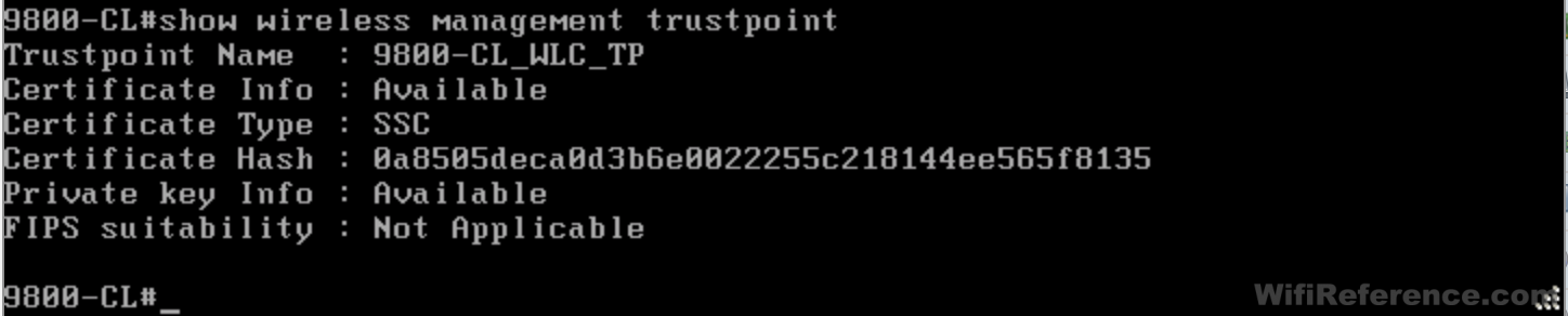
- Save the config with a “write mem” or “copy run start”. You can now access the GUI via the Management IP Address you configured. APs should now be able to join, as well.
Configuring the Catalyst 9800-CL when deployed from vCenter
Note: There are actually some significant differences in the configuration process, depending on whether you deployed the OVA with ESXi/OVFTool or vCenter
Why am I not using the Web GUI Interface? Because it won’t allow you to configure the WLC without using Gigabit1 as the OOB Management Interface. Besides, you wouldn’t use the GUI to configure a switch from scratch, would you?
- Power on the VM and open the console.
- Choose whether you want a Virtual (VGA) or serial console (reference the optional section above for configuring a network serial console)
- Wait several minutes while the initial provisioning scripts run
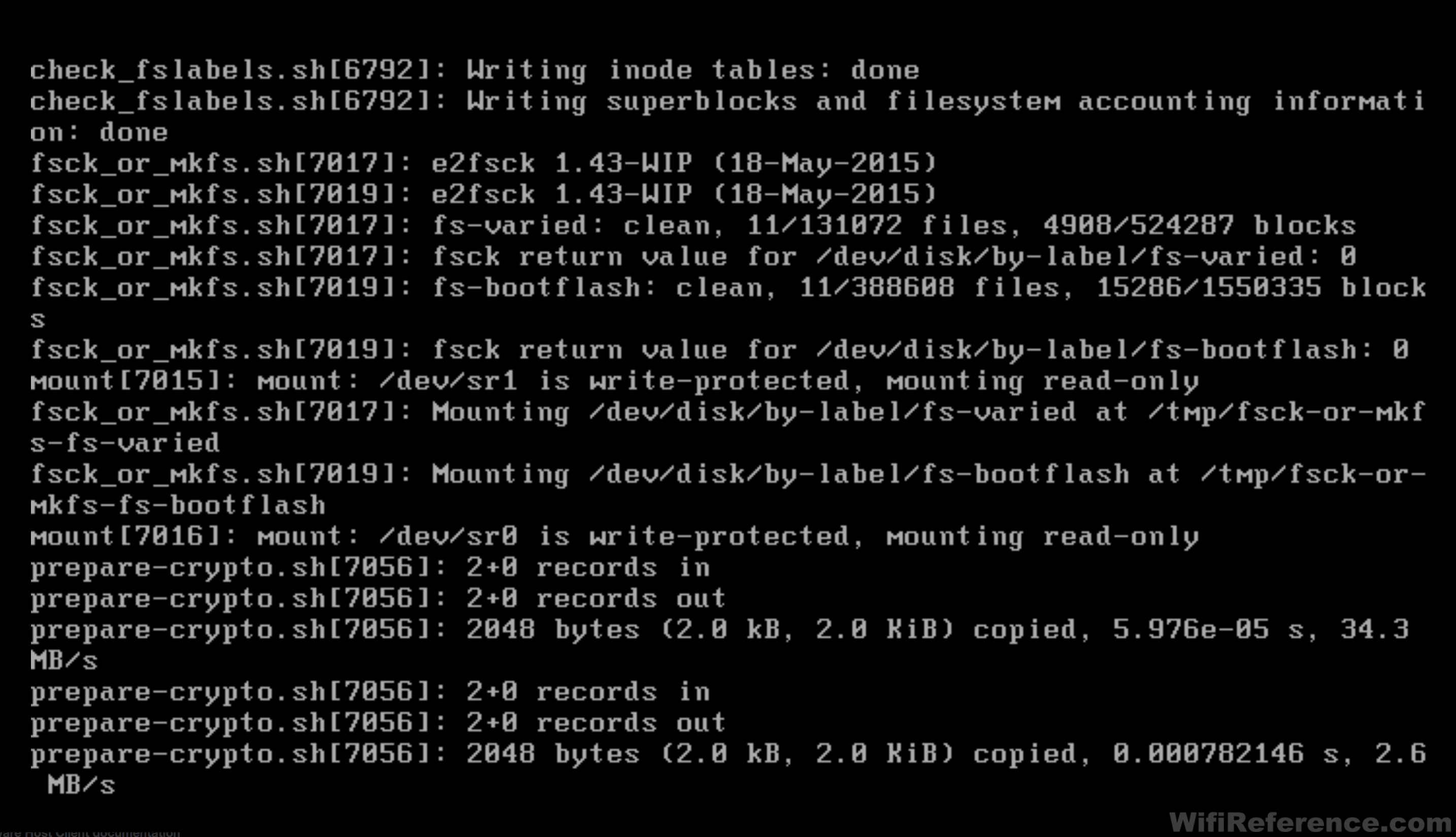
- The controller will reboot itself during this process
- Notice when the controller boots you will not see an initial config dialog box. This is because vCenter pre-configured the 9800 with the information you provided during the OVA deployment wizard. It will drop you straight to a command prompt.
- Enter enable mode (using the password you specified during the OVA deployment wizard) and then enter config mode. You will notice many status messages appearing on the screen as the controller continues to boot.
- This is where you will start to see the unfortunate side effects of deploying the VM with vCenter. Since the vCenter wizard doesn’t ask for VLAN information, it assumes you want the management IP address on the GigabitEthernet1 interface (as a routed port). Since most deployments will be using a trunked interface, this doesn’t make a whole lot of sense. It assumes you will be using at least two interfaces.
- Another unfortunate side effect is that it includes the interface name in the default route. You must remove this route before you reconfigure the GigabitEthernet1 interface or you won’t be able to remove it!
- Now let’s start with the initial configuration, which includes redoing some of what vCenter has configured.
Enable logging synchronous on the console
Set VTP mode to transparent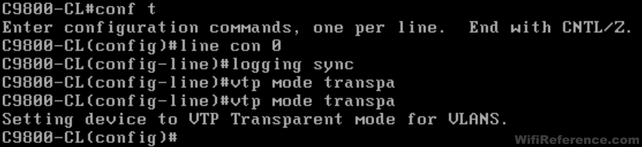
- Now let’s remove that default route (you must specify the interface when removing it)

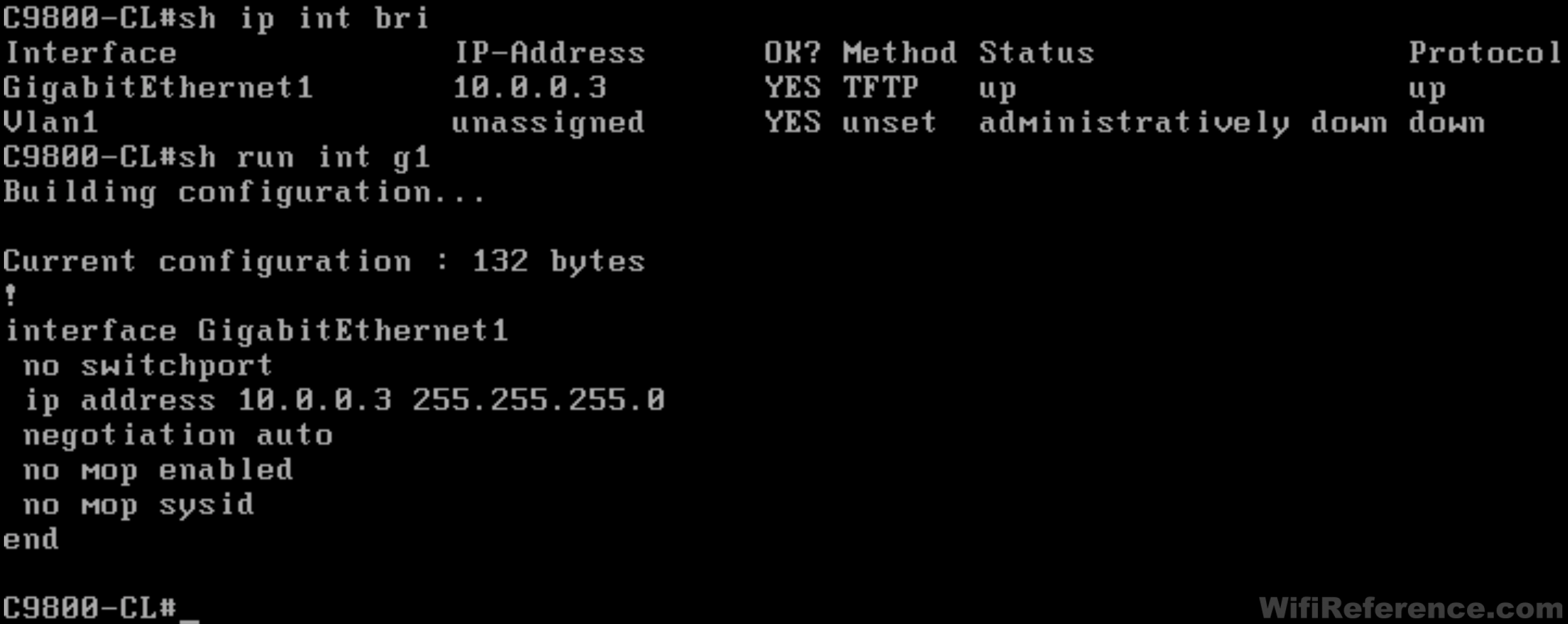
- Remove the IP address for interface GigabitEthernet1 and configure it as a switch port. Then set that switch port to trunk mode.
- Create your VLANs and interface VLANs, and assign IP addresses to them. Don’t forget to “no shut” them!
- Now let’s add that default route back, but this time we won’t specify the interface name

- Configure the wireless management interface and enable management via wireless

- Shut down the 2.4GHz and 5GHz bands so that we can configure the country code
- Configure the country code. Note: The country code must be in ALL CAPS! This command is also what prevents you from seeing the initial configuration wizard when you log in to the GUI.

- Bring the 2.4GHz and 5GHz bands back online
- Set the NTP server

- Check the status of your interface VLANs. They will most likely be in an up/down state.
- To bring the interface VLANs online, we need to disable and enable the GigabitEthernet1 interface by issuing a “shut” followed by “no shut”
- Now your interface VLANs should be online, in an up/up state
- Now that we have network connectivity, we can generate the self-signed certificate. This is the most important configuration step, because without a successful result of this command, APs cannot join the controller. Issue the following command (change the password at the end):
Note: This command is not entered in config mode.
wireless config vwlc-ssc key-size 2048 signature-algo sha256 password 0 <pwd>
- Once you issue the command, you will see a bunch of status messages on the screen.
- Verify that the certificate was created by issuing the following command. If your output looks similar to this, you are good to go.
- Save the config with a “write mem” or “copy run start”. You can now access the GUI via the Management IP Address you configured. APs should now be able to join, as well.
Paste-able Initial Configuration Script
Here is a script that you can paste into a freshly deployed Catalyst 9800-CL in order to give it an initial configuration. This is essentially the steps for the ESXi/OVFTool process. You’ll obviously need to modify the values to suit your environment. The items that need to be changed are italicized.
hostname C9800-CL-WIFIREFERENCE
line con 0
logging sync
vtp mode transparent
int g1
no ip addr
switchport
sw mo tr
vlan 1xx
name Management
vlan 2xx
name Clients
int vlan 1
no ip addr
shut
int vlan 1xx
ip addr 10.0.1xx.5 255.255.255.0
no shut
int vlan 2xx
ip addr 10.0.2xx.5 255.255.255.0
no shut
ip route 0.0.0.0 0.0.0.0 10.0.1xx.1
ena sec wifireference
user admin priv 15 sec wifireference
line vty 0 15
login local
wireless management interface vlan 1xx
wireless mgmt-via-wireless
!PAUSE HEREap dot11 24 shut!PAUSE HEREap dot11 5 shut!PAUSE HERE
ap country US!PAUSE HEREno ap dot11 24 shut
no ap dot11 5 shut
ntp server 10.0.0.1
int g1
shut
no shut
end
!PAUSE HERE AND WAIT FOR NETWORK CONNECTIVITYwireless config vwlc-ssc key-size 2048 signature-algo sha256 password 0 wifireference
!PAUSE HERE AND WAIT FOR CERT PROCESS TO COMPLETEshow wireless management trustpoint
Conclusion and Quick Configuration Tips
I hope this helps get your controller online with a trunked network interface. I intend to write another post that covers the new configuration model, and how to configure WLANs, tags, profiles and policies. In the meantime, here are a few quick tips for the main configuration of the Catalyst 9800:
- You will either need to enable the default Policy Profile, or create a new one. The default policy profile is disabled and will prevent your SSIDs from showing up on your APs.
- Client VLANs are assigned by the Policy Profile (on the Access Policy tab), not by the WLAN. The VLAN you want to assign to clients must exist in the 9800 before it can be assigned with a Policy Profile.
- Policy Profiles, Site Profiles and RF Profiles are each bound to APs with Tags. These Tags can be statically or automatically assigned.
- Be sure to enable Application Visibility and Device Profiling.
I’ll provide more details on each of those steps in the next post.
Is a SVI necessary for client traffic? I just made a setup with only L2 Vlan for the clients.
Just need a SVI for AAA interface override or DHCP proxy or not?
Great post ?
SVIs are not necessary for client traffic unless you are doing mDNS, Multicast or DHCP Proxy.
Can you provide documentation for this comment please? I am chasing my tail looking for info on why do SVI or not with 9800’s.
I don’t have any documentation handy to support it, but it is a pretty easy thing to test.
For centrally switched traffic, it is mandatory to configure a Layer 2 VLAN mapped to the SSID, but the corresponding Layer 3 interface (SVI) is optional, unless you need the multicast DNS (mDNS) feature or DHCP relay functionality. This is different from AireOS, in which a dynamic interface (Layer 3 interface and related IP address) is required.
From Cisco Catalyst 9800 Series Configuration Best Practices Guide.
Thanks for posting this. Great Job.
In the example’s I see that in vmware Gi1 and Gi3 are not used. In the later configuration of the 9800_CL you use Gi1. I must be missing something. Are Gi1, Gi2 and Gi3 interchangeable?
Sort of. It’s confusing. Deleting NIC1 and NIC3 (specifically those numbers) in VMware is just to reinforce the role for each NIC. If you delete them before you power it on, you can delete any two NICs you want and you will wind up with a single Gig1 in the 9800. In the 9800, the NICs are always numbered starting with 1, and will assume them in order from the lowest connected NIC in VMware. Does that help?
You can likely interchange G1 and G2, but G3 will be looked for if you put the controllers in HA. Instead of deleting them you can just uncheck the connect at power up box before you power it up. That way if you want to use a separate interface for distribution of clients rather than have them trunked off the management interface or deploy HA SSO they will be available. Just enable it instead of re-adding it. Security guys usually frown on client traffic and management traffic on the same interface although the 5520 and 8540 basically make it impossible to do so. For the 9800CL I have also discovered that configuring HA even in the 7.2 release does not show all interfaces in the GUI even if they are configured in VMware. HA needs to be configured from the CLI and WILL look for gigabit interface 3. A show IP interface Brief will show all interfaces. And when reading the Cisco docs on how to configure HA, their view of “priority” is not what you would expect. Priority 1 in the real world take precedence over everything else you do, priority 1 in Cisco’s HA world is the lowest value you can assign and will become a standby
Here’s a descent link on how to configure HA if you don’t see the correct interfaces in the GUI
https://www.cisco.com/c/en/us/td/docs/wireless/controller/9800/config-guide/b_wl_16_10_cg/high-availability.html#concept_6C8DB7891E764C869E5FC11349120C20
Hi Dave,
Nice article! Thanks for putting these together. Not sure if you know but all the guides I see are pretty much for VM version of the 9800 and always state the creating of the cert with –
“wireless config vwlc-ssc key-size 2048 signature-algo sha256 password 0 ”
Now is this specific to a Virtual controller or does the above also need to be done on physical controllers?
Cheers
This step only needs to be performed on virtual controllers. Hardware appliances use the MIC for this purpose.
Thanks, you article helped get going on an ESXi server. I am a newbie to this and still learning. I have a 2702 AP that I use in my lab, I noticed that even after choosing GB as country, it is stuck in UX regulatory mode. All the cisco documentation says to Prime the AP using a special mobile application called AirProvision. However I can’t find it on app store or play store. Would you happen to know if Cisco has totally dropped support for these AP’s (i-e 2702’s). These seems to be no way to prime it as it stands now.
Why we need to allow all VLANs on the trunk interface on vSwitch? Why not the ones which are required?
In ESXi, there is no way to limit the allowed VLANs. In vCenter this is possible, but in my experience it doesn’t actually completely remove the unwanted VLANs.
Hello
i am new in wireless network.
can i use it in real network or need to buy license for using real network?
You need to purchase a license for anything other than evaluation use.
Dave that is amazing!! Thank you for the guide!!
I have literally tried about 10 times (redeploying the OVF from scratch each time) and cannot get the “wireless config vwlc-ssc key-size 2048 signature-algo sha256 password 0 ” to work.
It gives me a decent amount of console output, including messages like “Trustpoint: wlc_WLC_TP created successfully”. However the script then seems to hang for several seconds and terminates with no further output. It does not say “script is completed” like in your screenshot.
Then when I run sh wireless management trustpoint, all the fields are blank as though nothing has been set.
I’ve tried other things in addition to following these instructions, like doing it through the web UI. It just doesn’t seem to work. Is there something I’m missing here?
Sorry for the late reply; I missed this comment. Does your controller have connectivity to the network when you’re running the command? I’ve seen a similar issue to what you’re describing when the WLC can’t reach its gateway or the network. I’m not sure why it causes this behavior, but it is something I have noticed.
Hey Davd, thank you so much for the guide. Save a lot of my time of research and there ain’t many in regards to using a flat subnet on the C9800, very much appreicated.
One question though, after I set the management IP on the SVI (vlan1), it is accessible on wired, but not on wireless. (I have turned on managment via wireless). Any idea?
Thanks
Eric
When you say it is pingable from the wired network, which VLAN are you pinging from? Check the native VLAN of the VM host. If the native VLAN is VLAN1, you will need to set VLAN1 as native on the 9800 (on the interface you are using as an uplink), or the switch will drop the frames tagged with VLAN1. Make sure the uplink interface is set as a switch port and not a routed port, since you are using an SVI. Also, make sure the wireless management interface is set correctly. Without knowing more about the config, this is all I can suggest.
Thanks for the reply.
My native VLAN of the VM host is VLAN1, and on 9800, I have set the Gi1 (which is the only interface I have under Ethernet) as a trunked switchport with native VLAN 1. Same as the wireelss management interface which is also on VLAN1.
This is the show ip result: https://freeimage.host/i/Jy1rInf
And the setting under Interface and Layer2:
https://freeimage.host/i/Jy14w0l
https://freeimage.host/i/Jy14P0Q
https://freeimage.host/i/Jy14tmF
Thanks
Eric